NFPA 25C Section 13.6: Backflow Prevention Assembly Testing and Maintenance
Quick Answer: NFPA 25C Section 13.6 sets expectations for testing and maintaining backflow prevention assemblies to verify they perform as intended. Compliance focuses on correct operation, measurable inspection results, proper maintenance intervals, and documentation that supports ongoing life safety and water system protection.
If your facility is trying to coordinate this work with broader fire protection services, a related starting point is Kord Fire Protection’s backflow testing for fire sprinkler systems and fire lines page, which fits naturally into the same maintenance conversation.
What NFPA 25C Section 13.6 requires in practical terms
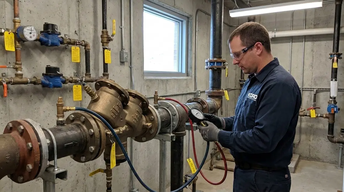
Commercial facilities rely on backflow prevention assemblies to protect potable water from contamination hazards created by normal building operations. NFPA 25C Section 13.6 backflow prevention assembly testing maintenance provides the framework for verifying that these assemblies continue to operate properly after installation, during routine service, and when conditions indicate elevated risk. In practice, compliance requires a repeatable process: inspection, functional testing, repair or part replacement when needed, and records that confirm the device is returned to service correctly.
Because backflow protection ties directly to both plumbing and fire protection water systems, many owners and facilities treat the testing program as part of the broader water based system assurance strategy. Facilities that already maintain their sprinkler and water based fire systems typically align backflow testing schedules with other water system maintenance to reduce downtime and streamline contractor mobilization. For background on overall water based system maintenance thinking, see NFPA 25 overview for complete water based fire protection systems maintenance breakdown.
How backflow prevention assemblies work, and why testing catches failures early
Backflow prevention devices reduce the risk that non potable or contaminated water can flow backward into the potable supply. The testing value comes from confirming that each internal component performs the required functions under controlled conditions, not just that the assembly is physically intact.
Common assembly mechanisms that drive test procedures
- Check valves: Must seal reliably and open and close as required by pressure conditions. Failures often show up as slow closing, leakage past the seat, or binding due to corrosion or debris.
- Relief and monitoring components: Where installed, these components confirm pressure behavior and response. Failures frequently relate to scaling, stuck moving parts, or improper reset behavior.
- Test cocks and bypass configurations: Many systems rely on test ports for measured verification. Missing, obstructed, or improperly valved test points can prevent accurate testing and may require corrective work before service.
- Strainers and in line fittings: Debris accumulation can change flow characteristics and valve response. Facilities sometimes overlook upstream maintenance, which can make backflow assemblies appear to fail prematurely.
In commercial and industrial environments, piping vibration, water quality variability, and intermittent construction activity increase the likelihood of early wear. Retail facilities often face different challenges, such as frequent tenant turnover and schedule pressure that can cause test access issues. Either way, testing aligned to NFPA 25C Section 13.6 backflow prevention assembly testing maintenance expectations is the mechanism that verifies the assembly remains reliable.
Inspection and test workflow aligned with Section 13.6 expectations
NFPA 25C Section 13.6 testing and maintenance is not simply a “visual check.” A credible program treats each backflow assembly as a system that must pass functional verification. A typical professional workflow includes preparation, field verification, testing, corrective action, and documentation.
1) Pre service preparation and site readiness
- Confirm device identification, model, configuration, and hazard classification responsibilities for the water system.
- Verify test kit calibration and that the proper pressure measurement method is used for the assembly type.
- Evaluate access and safety needs. Many failures go undiscovered because technicians cannot reach test cocks safely or because valves are not operable due to seized hardware.
2) Field inspection before functional tests
- Check for physical damage, corrosion, missing caps or covers, and signs of leakage.
- Verify that shutoff valves and related hardware allow the assembly to be isolated and tested as intended.
- Confirm that the assembly is installed with required orientations and supports. Stress from poor piping alignment can lead to internal seat degradation.
3) Functional testing and performance verification
Testing procedures focus on verifying that the assembly responds correctly to the required flow and pressure conditions, and that it meets established performance criteria for the device type. For many assemblies, the test process includes measuring differential pressure or flow behavior and confirming that each check component seals or relieves appropriately.
If measured results indicate leakage, delayed closure, or abnormal pressure response, maintenance and repair actions follow before the device is returned to service. A strong testing program also evaluates upstream conditions, because failures are often traced back to water quality issues or improper valve operation on the supply side.
4) Maintenance actions that restore reliability
- Replace elastomeric seals and worn internal components when performance indicates degradation.
- Clean internal passages and correct contamination causes where applicable, such as debris or scale accumulation.
- Restore proper function of test cocks and ensure they can be used again without obstruction.
- Re test after repairs to confirm the assembly returns to acceptable performance.
5) Documentation that supports ongoing compliance
Commercial stakeholders need test records that clearly identify the assembly, the date, the results, and corrective actions taken. This documentation supports inspections, insurance requirements, and internal audit readiness. For facilities that coordinate fire protection assurance, aligning backflow documentation with fire protection maintenance records can simplify compliance reporting and contractor oversight.
Facilities that want a broader view of how water based fire protection systems fit into maintenance programs can reference NFPA 13 overview for automatic fire sprinkler system installation to understand how system components and operational intent influence ongoing inspection and testing thinking.
Maintenance intervals and the real world variables that change outcomes
Section 13.6 expectations require testing at defined intervals and whenever conditions indicate the assembly may no longer perform properly. However, the actual maintenance burden often shifts based on site conditions, water quality, and operational realities. The best programs treat “routine schedule” and “condition based triggers” as a combined strategy.
Triggers that commonly increase the need for maintenance attention
- Water quality changes: Higher sediment load, new disinfectant chemistry, or seasonal temperature swings can affect valve seat performance.
- Construction or piping modifications: Work in mechanical rooms can disturb valves, test ports, or piping supports.
- Repeated nuisance alarms or pressure complaints: These can correlate with check valve sticking or abnormal pressure response.
- Observed leaks or recurring test failures: Small leaks can worsen rapidly, especially where corrosion accelerates under poor drainage conditions.
- Tenant changes and access gaps: Retail facilities often experience delayed maintenance responses when access is controlled by tenants.
Why many facilities underperform on access and valve operability
A frequent commercial compliance challenge is not the testing method. It is the ability to isolate, access, and test without causing system downtime or safety risk. Assemblies may be installed behind ceilings, in locked rooms, or under equipment that restricts safe technician movement. Even when the assembly is tested on time, valves and test cocks that are seized or obstructed can prevent accurate functional verification. Addressing those access issues early typically reduces repeat visits and improves overall compliance stability.
Common failure points to watch during backflow testing and maintenance
Backflow assemblies do not usually fail without indicators. The testing process should be treated as the method to confirm what site conditions are already hinting at, such as leakage, inconsistent pressure response, or abnormal actuation behavior.
High frequency issues seen in commercial settings
- Seat leakage: Often caused by debris, corrosion, or worn sealing surfaces. This frequently presents as pressure loss or inability to hold required conditions during test.
- Sticking check valves: Caused by scale buildup, sediment, or misalignment due to stress from piping.
- Failed or damaged test cocks: Obstructed caps, damaged threads, or improper valve positions reduce test accuracy and create operational delays.
- Improper upstream conditions: Missing strainers or poorly maintained filters increase the debris that reaches internal components.
- Incorrect reassembly after prior service: Incorrect torque, wrong parts, or improper reinstallation of internals can lead to repeat failures even after replacement work.
Technicians who work across commercial, industrial, and retail water systems tend to see the same themes repeatedly. The program succeeds when it combines correct testing technique, effective maintenance, and attention to the installation details that influence component longevity.
For additional water system context that can inform how facilities coordinate maintenance across fire protection and water utilities, see Kord Fire Protection’s NFPA 25 maintenance breakdown and fire sprinkler code considerations in California explained.
Why partnering with a commercial backflow service provider matters
Backflow testing and maintenance must be performed with the correct tools, documented results, and the practical ability to repair or coordinate repairs without creating system risk. Kord Fire Protection supports commercial compliance programs by integrating backflow assurance with water based fire protection maintenance planning. That approach helps facilities reduce scheduling conflicts, improve access readiness, and maintain consistent documentation across related systems.
For organizations that also manage fire pump water supplies and other pressure dependent equipment, the discipline of coordinated water system maintenance matters. Industry background and resources from groups focused on fire protection systems and water infrastructure can support broader planning; see firepumps.org.
Owners and facilities typically benefit when their service partner treats backflow assemblies as critical life safety water control points, not as isolated plumbing components. When NFPA 25C Section 13.6 backflow prevention assembly testing maintenance is treated this way, the facility achieves higher reliability, fewer repeat failures, and stronger audit readiness.
Frequently Asked Questions
Call to action
Facilities that need reliable compliance for NFPA 25C Section 13.6 backflow prevention assembly testing maintenance should schedule a professional inspection and test program now. Kord Fire Protection can help align backflow assurance with your broader water based fire protection maintenance plan, address access and operability issues before testing dates, and provide documentation that stands up to audits. Contact Kord Fire Protection to confirm your current schedule, device types, and next maintenance actions.

Join Our Newsletter!
Get the latest fire safety tips delivered straight to your inbox From our Newsletter.