NFPA 25C Section 13.5: Pressure Reducing and Relief Valve Inspection Guide
Quick Answer
NFPA 25C Section 13.5 pressure reducing relief valve inspection focuses on verifying correct valve operation, setpoints, travel, and proper discharge function. The process typically includes visual checks, functional testing where required, and documentation of results to maintain reliable water supply performance.
Facilities that want a practical companion to this topic can also review standpipe pressure reducing valve maintenance, which fits naturally into the same inspection and calibration conversation.
What NFPA 25C Section 13.5 requires in plain language
NFPA 25C Section 13.5 addresses maintenance and inspection practices for valves that reduce incoming pressure and manage excess pressure through relief functions. In commercial and industrial water based fire protection systems, these devices protect downstream components, maintain design pressure at sprinklers, and reduce the risk of system pressure instability during demand.
This NFPA 25C pressure reducing relief valve inspection guidance is not limited to “looks good from the outside.” It expects technicians to confirm the valve’s operational health, verify that controlled pressure remains within intended limits, and ensure relief paths are not obstructed, improperly configured, or unable to respond when pressure rises.
Where pressure reducing and relief valves fit in a facility’s fire water supply
In many commercial facilities, especially those with mixed floor elevations, cross site zone demands, or supply from multiple sources, pressure reducing and relief valves help keep system pressures within safe and effective operating ranges. They also support stable performance during pump cycling and hydrant or sprinkler system demand.
Common installation patterns include pressure reducing stations or valve arrangements serving:
- Standpipe systems with varying elevation heads
- Sprinkler zones where upstream supply pressure exceeds design limits
- Dedicated water supply loops requiring tighter pressure control
- Buildings with booster sets where relief logic prevents harmful overshoot
For broader context on system maintenance expectations that often include upstream and downstream interactions, facilities commonly align their valve work with the same compliance discipline used for water based systems, as described in Kord Fire Protection’s maintenance focused resources like NFPA 25 overview for complete water based fire protection systems maintenance breakdown.
How the inspection process works: step by step operational checks
A strong NFPA 25C Section 13.5 pressure reducing relief valve inspection program follows a repeatable order. That order reduces missed defects, supports faster triage, and produces defensible documentation for AHJs and internal audits.
1) Pre inspection readiness and safety controls
Technicians first confirm system status, isolate work areas, and verify that temporary shutdown or impairment procedures follow local requirements. Pressure reducing and relief valves can affect system pressure stability, so the plan considers downstream criticality, fire watch needs when required, and coordination with the building’s fire alarm and monitoring strategy.
2) Visual condition and configuration verification
Visual inspection typically includes:
- Confirming valve labeling, identification plates, and setpoint indications (when present)
- Checking for corrosion, leaks, damaged sensing lines, or evidence of tampering
- Verifying relief discharge routing is open, unobstructed, and terminated safely
- Examining supports, strainers, or associated components that can restrict flow
- Ensuring caps, covers, and access components are installed correctly
3) Setpoint and pressure control verification
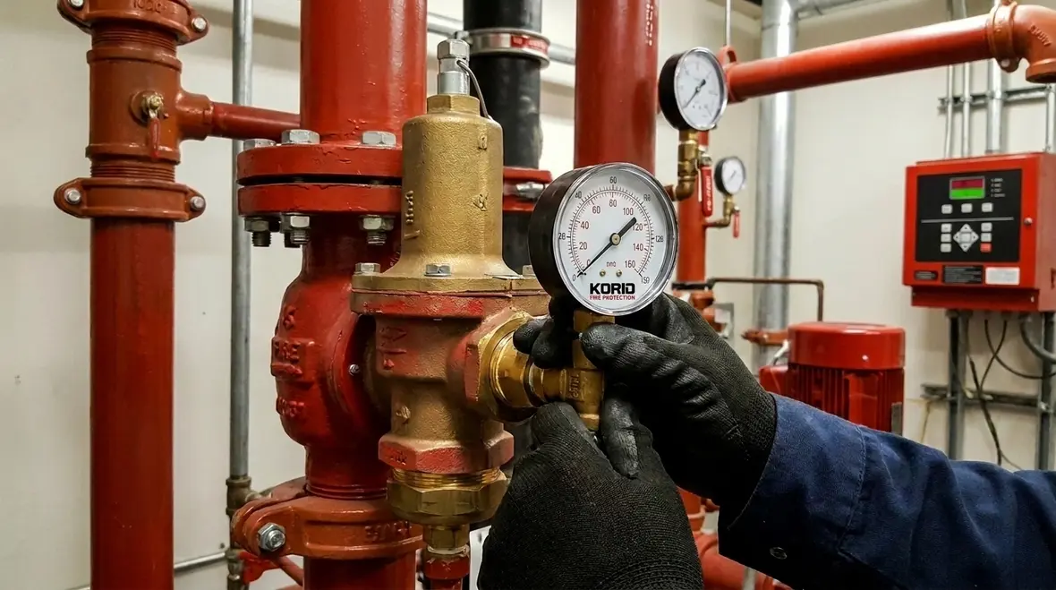
Pressure reducing valves must maintain controlled downstream pressure under varying demand conditions. Technicians verify setpoints using calibrated test gauges and prescribed test taps. The goal is confirming the valve stabilizes pressure rather than oscillating due to internal contamination, wear, or improper actuator function.
Where the valve design includes sensing elements, pilot lines, or external controllers, inspection extends to:
- Condition of sensing lines and fittings
- Absence of blockages or restrictions
- Integrity of control components
4) Relief function readiness and response assessment
The relief portion of the arrangement protects the system when pressure rises above the valve’s intended control range. Inspection must confirm that relief paths are not closed, capped, or routed in a way that defeats discharge. Technicians also assess whether the relief element can respond to excess pressure without sticking.
In practice, many failures occur as “functional invisibility.” The relief function sits idle under normal conditions and only reveals defects during abnormal pressure events. That is why documented checks for discharge path integrity and internal condition matter.
5) Functional testing and performance confirmation (where required by the applicable inspection procedure)
Depending on the valve type and system arrangement, functional tests confirm that the valve responds as intended. This can include staged pressure checks and controlled observation of stability and response. Any abnormal behavior such as hunting, delayed response, or abnormal discharge patterns triggers escalation to cleaning, repair, or replacement.
Commercial facilities often pair this approach with comprehensive code aware planning for sprinkler installation and system design considerations. For foundational understanding of water based system installation elements that influence later valve operation, Kord Fire Protection also provides a related overview: NFPA 13 overview automatic fire sprinkler system installation.
Common failure points that show up during pressure reducing relief valve inspection
Experienced inspection teams typically see the same defect categories across commercial, retail, and industrial occupancies. The defects can be subtle at first and still cause noncompliant performance during a real demand.
Sticking, contamination, and internal wear
Debris from system installation, scale, and long term water chemistry can obstruct seats and moveable elements. Even small deposits can shift the setpoint behavior, causing pressure drift or intermittent relief.
Relief discharge path problems
Relief discharge lines get modified for convenience, capped “temporarily,” or rerouted without considering required free discharge. Blocked relief routing can lead to unsafe pressure conditions downstream when the valve needs to protect the system.
Instrumentation and sensing line issues
Some valve designs depend on pilot pressure, sensing lines, or external controls. Leaks, kinks, misrouting, or clogged sensing ports cause delayed response and incorrect control behavior.
Gauge calibration and test method drift
Setpoint confirmation depends on calibrated measurement tools and consistent test procedures. Inconsistent gauge placement or use of uncalibrated equipment leads to questionable results and unreliable compliance reporting.
Documentation that stands up to AHJ and insurer review
Documentation is where many facilities either gain compliance confidence or lose it. A strong inspection record includes what was checked, what was measured, what the observed operating behavior was, and any corrective actions taken. The record should clearly connect inspection outcomes to valve performance expectations.
For best practice, include:
- Valve identification, size, and location
- Inspection date, technician identification, and system status assumptions
- Visual condition findings and leak observations
- Pressure measurements used to verify control stability and relief readiness
- Functional test results when performed and the observed response characteristics
- Corrective actions, parts replaced, and any retest confirmation
Kord Fire Protection supports commercial teams that need consistent reporting across multiple assets. Where water supply and system maintenance programs must stay coordinated, this documentation discipline aligns well with the broader maintenance breakdown guidance in NFPA 25 overview complete water based fire protection systems maintenance breakdown.
Scheduling and compliance strategy for commercial facilities
Pressure reducing relief valve inspection is rarely isolated. It must fit into a larger maintenance cadence that considers system water demand patterns, seasonal use, contractor staffing, and equipment criticality. Commercial properties typically benefit from:
- Coordinated shutdown planning with other system tests to reduce repeat disruption
- Seasonal awareness when water demand and operating conditions shift
- Prioritizing valve stations that feed the most sensitive zones or highest hazard areas
- Trend tracking across recurring inspections to detect drift before failure
When facilities operate across jurisdictions, understanding code context becomes important. For teams managing compliance in California, Kord Fire Protection provides additional context in fire sprinkler code California explained.
To keep the program accurate and audit ready, facilities also align their approach with dependable guidance sources such as Firepumps.org, especially when pressure management interacts with pump operation, setpoint ranges, and system stability.
Frequently Asked Questions
Call to action
Pressure reducing and relief valve performance directly impacts system stability during real demand, not just compliance paperwork. Kord Fire Protection helps commercial, industrial, and retail facilities plan and execute NFPA 25C Section 13.5 pressure reducing relief valve inspection with disciplined testing, calibrated measurement, and audit ready documentation. Schedule your next valve inspection and maintenance window with Kord Fire Protection to reduce service interruptions, prevent pressure control drift, and keep your water based fire system operating as designed.

Join Our Newsletter!
Get the latest fire safety tips delivered straight to your inbox From our Newsletter.