Sprinkler System Hydraulic Calculations Basics for Architects
For architects, sprinkler system hydraulic calculations basics start with a simple goal: predict water flow and pressure at every sprinkler so the system discharges as the code requires. In practice, this means sizing pipe losses, selecting sprinkler types, and checking that the most demanding area still meets the required density and duration. Then, those numbers get translated into drawings, room by room, so the contractor can install the system without turning the job into a guessing game.
Kord Fire Protection Technicians often explain it this way: if the hydraulics are wrong, the sprinkler heads do not fail politely. Instead, they spray too little, too late, or not where the design expects. And no architect wants the fire marshal to treat their drawing like a horoscope. With that in mind, this guide walks through the thinking process that supports clear, buildable design. It also helps connect the report to what architects actually draw and coordinate, because the math only matters if the project team can use it. When that bridge between calculations and plans is missing, the job tends to collect revisions, awkward emails, and the kind of meeting where everyone nods while quietly wondering who changed the ceiling heights.

What architects need to know about fire sprinkler hydraulic design
When architects read a hydraulic report, they should treat it like a map, not a math contest. The report links the building layout to water supply behavior. First, the design chooses a fire sprinkler demand. Next, it builds a hydraulic path from the water source through the piping to the most critical sprinklers. That path tells the story of how the system is expected to perform when the pressure is on, literally and professionally.
To move from concept to coordination, the architect focuses on practical impacts. The calculations influence pipe sizes, ceiling space needs, routing, and backflow or fire department connections. Therefore, early questions like where the water supply enters and which zones share the riser become important. Kord Fire Protection Technicians often advise architects to ask for the design basis before the first plan set locks in, because later revisions can ripple through structural and life safety coordination.
Think of the report as a coordination tool
Also, it helps to remember the real world. A sprinkler system does not care about brand names, fancy ceilings, or that one tenant who insists the pipes can just go around. Hydraulics care about resistance, friction, elevation, and demand. If the reflected ceiling plan changes, if the soffits deepen, or if a corridor suddenly becomes the route for three trades instead of one, the hydraulic picture can change too. That is why many teams benefit from reviewing broader coordination topics early, especially when multiple systems are competing for the same space. Kord Fire’s guide on fire protection systems components and coordination is a helpful companion when architects need that wider systems view.
How the demand area gets selected and why it matters
Fire sprinkler design typically starts by choosing a demand area that represents the worst case within the building. Then the system assumes sprinklers operate in a defined pattern for a set time. As a result, the calculated water flow and pressure reflect the peak requirement, not the average one. This is one of the first places where a small assumption can quietly become a very expensive problem later.
Architects often influence this decision without realizing it. For example, the choice of ceiling type, obstructions, room geometry, and fire separation details can change which sprinklers are considered in the most critical area. Additionally, rack storage, high bay spaces, and complex ceiling finishes can shift the effective coverage and demand assumptions. The building may look calm and orderly on paper, but hydraulically, a few inches here and a few obstructions there can change the scenario that governs the whole layout.
Kord Fire Protection Technicians explain this step with a calm but firm tone: the demand area selection is where design intent either survives or gets crushed. If the design team selects the wrong scenario early, the rest of the hydraulic workflow will faithfully calculate the wrong answer, and everyone will suffer. Nobody wants that, not the contractor, not the sprinkler shop, and definitely not the person stuck explaining it at a coordination meeting. Teams dealing with permit packages and review comments can also benefit from Kord Fire’s article on the new construction fire protection submittal checklist, especially where hydraulic documentation needs to align with the drawings.
Understanding pressure losses: friction, fittings, and elevation
Once the demand area exists, the calculations track pressure losses along the hydraulic path. The two big buckets are friction loss in piping and added loss from fittings and changes in direction. Then elevation loss enters when the water must lift to reach sprinklers at higher floors or ceilings.
In everyday language, the system has a limited energy budget. Every bend, elbow, valve, reducer, and pipe segment spends part of that budget. Therefore, the report’s pipe schedule and fitting counts become more than trivia. They affect the final pressure at the sprinkler. This is also why plan changes that appear innocent on an architectural sheet can make a sprinkler designer reopen the hydraulic model with the expression of someone who just discovered one more hidden revision.
Why ceilings and routing choices matter more than they seem
Architects should coordinate ceilings and soffits with this in mind. If a design places sprinkler mains in a low clearance zone, the team may route larger pipe closer together or use more fittings than planned. Consequently, the friction and fitting losses can rise, which may force changes in pipe diameter or flow requirements. When that happens late, it feels like moving furniture after the house is already staged. It can be done, but the contractor will make a face that says, Really? A solid baseline understanding of sprinkler behavior also helps here, and Kord Fire’s fire sprinkler overview and system guide gives useful context for architects who want the bigger picture without drowning in technical shorthand.
Framing the water supply and system flow requirements
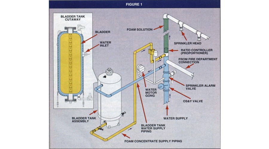
Hydraulic calculations must connect system demand to available water supply. That means the design checks static and residual pressure at the point of connection, then compares supply curve behavior under flow. If the supply cannot meet demand, the system needs revisions such as a different sprinkler layout, pipe sizing changes, or fire pump and tank strategies.
Architects play a key role here through space planning. Fire pumps, controllers, and tanks require rooms with proper access, ventilation, and clearances. Backflow devices and fire department connections need safe and reachable locations. Moreover, the building layout can affect which risers and supply mains serve specific areas. If the design heads toward a condition where municipal supply alone is not enough, the team should coordinate early with the dedicated fire pump service page in mind, because pump support is not something you want to discover after the room schedule is already squeezed to perfection.
Kord Fire Protection Technicians often stress that the water supply piece must align with the hydraulic narrative. If the report assumes one connection pressure but the building design later changes the supply routing, the calculations lose credibility. So, architects should request the exact water supply input used in the report and verify it stays true through construction documents. Related water supply planning issues also show up in Kord Fire’s fire hydrant water supply system design guide, which reinforces how static pressure, residual pressure, and friction losses work together in real system design.
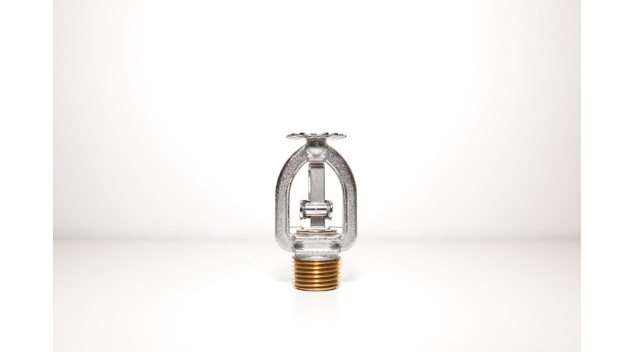
Interpreting sprinkler selection, spacing, and obstruction rules
Sprinkler performance depends on the head type, its K factor, temperature rating, orientation, and spray pattern. Yet in real building design, sprinkler choices rarely stay head only. They interact with spacing rules and ceiling obstructions.
For example, a ceiling with beams or soffits can create zones where water distribution changes. Therefore, the design might adjust sprinkler location, choose different head styles, or modify the coverage assumptions. The report reflects these decisions through the number of sprinklers in the demand area and the flow per head required. For architects, the practical lesson is simple: the more clearly the ceiling and obstruction story is told, the less rework the sprinkler designer has to do later.
Architects can support clean hydraulic outcomes by providing clear ceiling information early. If they delay specifying ceiling height, beam depth, or soffit layouts, the sprinkler engineer may need to re-run computations after design development, which wastes time and budget. Kord Fire Protection Technicians explain it with practical humor: when the ceiling is a mystery, the hydraulics become fortune telling, and nobody should build life safety on vibes.
Where architects coordinate with sprinkler designers during plan sets
Hydraulic calculations succeed when drawings and reports agree. Architects should plan for coordination across multiple layers: reflected ceiling plans, piping layouts, room finishes, and structural penetrations. Then the design team confirms that the hydraulic path used in the report matches the routed piping shown on plans.
Several details need confirmation. First, the pipe sizes shown on plans should match the report. Next, valve locations, check valves, and inspector test connections must reflect the same configuration the hydraulic model uses. Also, the most remote sprinkler must align with the critical section identified in the calculations. These are small details right up until they are not. On the day of review, they become the entire conversation.
Even the best calculations can trip over small drawing gaps. A mislabeled main or a missing elbow callout changes the fitting count, and that changes pressure loss. Consequently, the final sprinkler discharge can drift from what the design intended. To avoid this, architects should ask for a coordination checklist during design development, and Kord Fire Protection Technicians can help the team catch mismatch risks before submittals pile up like a stack of almost correct documents.
FAQ
Conclusion
Fire sprinkler hydraulic work becomes a lot easier when architects treat it like a design tool, not a final paperwork chore. When they align ceiling layouts, pipe routing, and water supply assumptions with the sprinkler system hydraulic calculations basics, fewer surprises show up during inspection. Kord Fire Protection Technicians recommend early coordination, clear documentation, and a single source of truth between report and drawings.
If the team wants help translating the hydraulics into clean plan sets, contact Kord Fire Protection for a design coordination review and keep the project moving. Where water supply strategy points toward pump support or related infrastructure, the fire pump service page is a strong place to continue the conversation near the end of design and into construction coordination.
Join Our Newsletter!
Get the latest fire safety tips delivered straight to your inbox From our Newsletter.