NFPA 25C Section 9.5: Automatic Tank Fill Valve Inspection and Testing
Quick Answer
NFPA 25C Section 9.5 governs how facilities inspect and test automatic tank fill valves that support water supply for fire protection systems. It focuses on verifying valve operation, preventing failure due to contamination or misadjustment, and ensuring the fill cycle performs as intended under normal and off normal conditions.
Facilities managing broader compliance tasks can also review Kord Fire Protection’s full fire protection services for related inspection, maintenance, and readiness support.
What NFPA 25C Section 9.5 is trying to prevent
Automatic tank fill valves are designed to keep fire protection water tanks replenished to the required level. NFPA 25C Section 9.5 automatic tank fill valve inspection testing addresses one central risk: a fire protection system losing effective water supply because the fill valve fails to open, closes unexpectedly, or cannot maintain the intended tank level.
For commercial, industrial, and retail facilities, the compliance challenge often is not simply the act of testing. The challenge is repeatability. Valves can drift due to scale, debris, corrosion, or tubing leaks. Control components can stick because the system sits idle most of the time. NFPA 25C Section 9.5 automatic tank fill valve inspection testing helps maintenance teams detect those issues before they become operational failures during an emergency.
Where automatic tank fill valves fit in the water supply chain
Automatic tank fill valves usually operate as part of a tank supported fire protection water supply arrangement. They coordinate with tank controls and water level sensing devices so that the tank refills when it drops below a set point.
In practice, these valves may interface with components such as:
- Float controls and level switches that initiate fill
- Strainers or regulators that protect valve seating and flow stability
- Check valves that prevent backflow into a supply source
- Alarm or supervisory circuits tied to water supply status
If any adjacent component behaves incorrectly, the fill valve can appear to “work” during a visual check while still failing the functional intent of NFPA 25C Section 9.5. This is why inspections focus on condition and operation, not appearance.
Core requirements in NFPA 25C Section 9.5: inspection first, then functional verification
NFPA 25C Section 9.5 automatic tank fill valve inspection testing typically follows a two phase approach: verify physical condition, then verify operational performance against expected behavior. A competent test method ties what the valve does to what the tank level controls and system design intend.
1) Inspection items that frequently reveal hidden problems
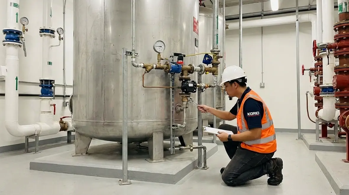
During inspection, technicians commonly prioritize findings that correlate with valve failure modes. Typical high value checks include:
- Valve trim and seating condition: Scale, corrosion, and debris can prevent full closure or full opening.
- Strainers and filters: Partial clogging can slow the fill cycle or cause intermittent operation.
- Interlocks and sensing lines: Stuck floats, sluggish level sensing, or obstructed tubing can falsely call for fill or prevent it.
- External leaks: Leaks around the packing, flanges, or connections can reduce reliability and create false supervisory signals.
- Support and alignment: Misalignment can increase friction and degrade repeatability of valve movement.
Commercial maintenance teams sometimes skip detailed trim inspection because the valve is not frequently operated. NFPA 25C Section 9.5 automatic tank fill valve inspection testing is intended to close that gap by requiring attention to the components most likely to degrade while idle.
2) Testing methods that verify the valve performs as designed
Functional testing generally aims to confirm that the fill valve responds correctly to tank level control signals and achieves expected fill operation. This can include verifying:
- Correct opening response: The valve opens when the tank level control indicates fill is required.
- Correct closing response: The valve closes when the tank reaches the intended level set point.
- Stable operation: The valve does not cycle excessively or stall mid travel due to contamination or control instability.
- Absence of abnormal flow behavior: No unintended overflows or continual minor discharge that indicates seating issues.
Because testing can impact water supply parameters, many facilities coordinate test windows to avoid unintended effects on system monitoring. The approach should align with facility procedures and any system design constraints.
Common failure points found during inspection and testing
NFPA 25C Section 9.5 automatic tank fill valve inspection testing often uncovers patterns that repeat across many facilities. Understanding these failure points helps teams plan corrective actions and reduce recurrence.
Sticking or sluggish valve movement
Sticking can result from scale, corrosion, or residue on seats and stems. Sluggish movement may also come from damaged control linkages or restricted passages in the valve trim.
Strainer clogging and flow restriction
Strainers catch debris, but they also accumulate it. Reduced flow can delay refill and can create conditions where the tank level fails to recover on schedule after a system demand.
Incorrect control set points and drift
Float assemblies or level switch settings can drift over time due to wear, contamination, or mechanical changes. Even small set point changes can shift when the fill valve cycles.
Leaking seats or packing deterioration
Seat leakage might not be obvious during visual inspection. Functional testing can reveal slow continuous flow or failure to hold the tank at the intended level.
Interdependency issues with alarms and supervisory signals
Facilities often depend on supervisory monitoring for water supply status. If the sensing or wiring logic is inconsistent with valve operation, operators can receive alarms that do not accurately reflect actual tank conditions.
For broader water based fire protection maintenance context, facilities can also review best practices outlined in Kord Fire Protection resources such as NFPA 25 overview and complete water based fire protection system maintenance breakdown.
How to document compliance for commercial facilities and audits
Inspection and testing must generate usable records that support ongoing compliance. For audit readiness, documentation should clearly show what was inspected, what was tested, what conditions were found, and what corrective actions were taken.
High quality records typically include:
- Asset identification: valve location, size, model, and tank identifier
- Date and time of testing, including any operational constraints
- Inspection observations: condition of strainer, trim, sensing lines, and visible leakage
- Test results: valve response to level control demand and release behavior
- Measured outcomes where applicable: tank level behavior and time to recover
- Corrective actions: parts replaced, cleaning performed, adjustments verified
- Follow up verification: re test after maintenance to confirm restored reliability
Commercial facility managers should also ensure that maintenance personnel coordinate with monitored systems so that any temporary changes during testing do not create confusion in alarm workflows.
For California facilities, related installation and maintenance context can be found in Fire sprinkler code California explained.
Implementation guidance: building a repeatable test and maintenance program
Compliance succeeds when procedures are repeatable and tied to equipment condition. A practical program for NFPA 25C Section 9.5 automatic tank fill valve inspection testing usually includes:
- Pre inspection preparation: confirm access, verify valve labeling, and confirm monitoring and control interfaces
- Controlled functional testing: execute test steps that validate open and close performance without creating unintended system impacts
- Targeted cleaning: clean strainers, remove deposits from accessible trim, and restore proper flow paths
- Adjustment verification: confirm level control set points remain within design intent after service
- Post test verification: confirm stable tank level behavior and ensure no abnormal leaks or cycling remain
As part of a broader approach to water based fire protection systems, Kord Fire Protection aligns maintenance practices with system design intent and common inspection risks. Facilities that manage ongoing compliance often benefit from establishing a documented cadence that includes both sprinkler system and water supply equipment. For sprinkler system installation context, see NFPA 13 overview automatic fire sprinkler system installation.
Where electrical and control interfaces influence valve behavior, coordination with Kord Electric can support reliable supervisory integration. For additional industry education resources, fire pump and water supply references are available at firepumps.org. Learn more from Kord Fire Protection also at kordfire.com.au and kordelectric.com.
Frequently Asked Questions
Call to action
Facilities that want defensible compliance should schedule NFPA 25C Section 9.5 automatic tank fill valve inspection testing with a qualified commercial fire protection provider. Kord Fire Protection helps teams plan repeatable procedures, address common failure points, and maintain audit ready documentation. Contact Kord Fire Protection today to confirm your tank fill valve inspection and testing scope, coordinate any operational constraints, and restore full reliability before problems escalate.

Join Our Newsletter!
Get the latest fire safety tips delivered straight to your inbox From our Newsletter.