NFPA 14 Section 15.5: Designing Maritime Standpipe Systems
Quick Answer: NFPA 14 Section 15.5 sets design expectations for standpipe systems intended for maritime service. It drives requirements for reliable fire water delivery, appropriate piping arrangement, functional performance, and coordination with shipboard and shore side firefighting operations.
For facilities evaluating standpipe performance, maintenance planning, or installation strategy, understanding the purpose behind NFPA 14 standpipe and hose installation rules helps frame why maritime system design decisions have to be practical, testable, and ready for real firefighting conditions. ([kordfire.com](https://kordfire.com/nfpa-14-section-1-2-the-purpose-behind-standpipe-and-hose-system-installation-rules/?utm_source=openai))
Why Section 15.5 Matters in Maritime Standpipe System Design
Maritime fire scenarios differ from many land based installations because vessel layout, onboard firefighting tactics, and connection points must work together under constrained conditions. NFPA 14 Section 15.5 focuses the maritime standpipe system design toward dependable water delivery, predictable pressure at the hose stations, and robust maintainability despite corrosion exposure, vibration, and limited access for inspection.
Commercial owners and facility managers typically approach these systems as engineered fire protection life safety equipment. However, compliance challenges often appear late in the project when integration details are missing: pump performance data, hose station routing, valve accessibility, and inspection access clearances. Addressing these issues during design avoids operational failure and reduces costly retrofit work.
What NFPA 14 Section 15.5 Requires the Design Team to Decide
Section 15.5 does not treat a maritime standpipe system as a generic piping network. It requires design decisions that preserve performance under real maritime constraints. The design team typically must confirm the following areas before drawings reach final issue.
1) Water supply concept and pressure performance
Maritime systems must deliver water to hose stations with adequate pressure and flow for expected firefighting use. Designers must establish the available pressure at the shore connection or onboard pump, the expected friction losses in vertical and horizontal runs, and the resulting pressure at the outlets under credible demand.
In practice, the failure mode is rarely “no water.” It is underperforming water pressure at the hose station during peak demand or with a clogged strain basket, partially closed valve, or a non functioning pump controller. Good design includes the hydraulic basis and the operational basis that maintenance teams can verify.
2) Piping arrangement suited to vessel layout
Shipboard geometry drives routing decisions. Designers must plan for minimal dead legs, controllable branch lines, and practical access for inspection and maintenance. Piping supports and hangers also matter because vibration and thermal cycling can loosen fasteners or create misalignment that accelerates corrosion or induces leaks.
3) Hose connection strategy and station placement
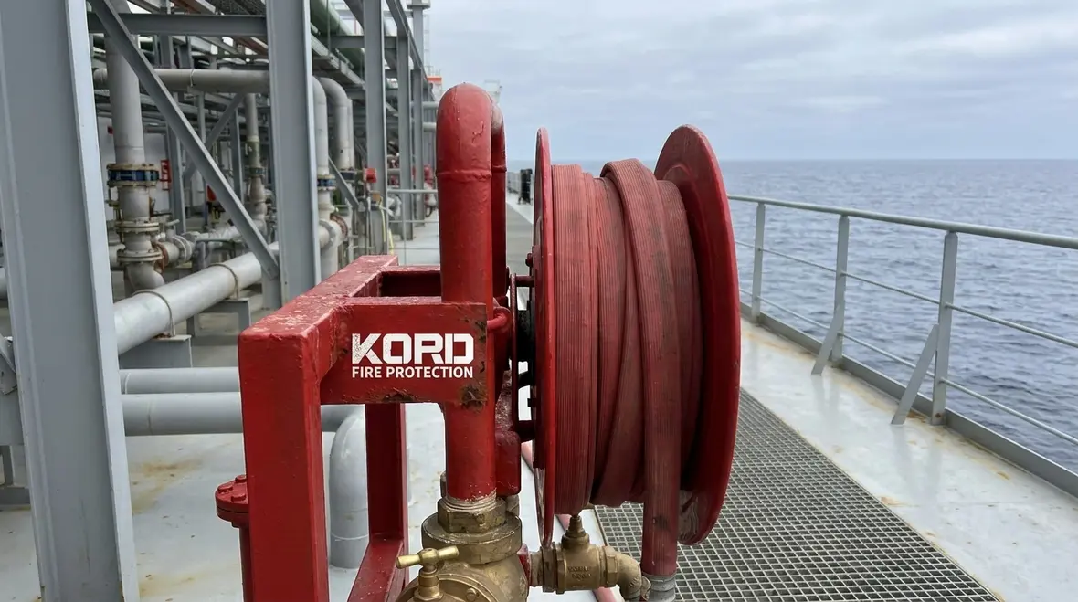
Hose stations must be positioned so responders can reach them and deploy hose without unacceptable delay. Designers must also consider how responders will advance toward the fire, how obstructions will affect hose length, and how the system design will support training and drills. A correct location on paper can still fail if it cannot be accessed during typical operations.
Key Components That Affect Reliability (and Common Failure Points)
Maritime standpipe systems depend on the correct function of valves, piping materials, hose outlets, and connection devices. During compliance reviews, teams often focus on hydraulics first. Yet operational failure frequently comes from component level issues.
Valves and isolation points
Valves must maintain system integrity and allow safe sectional control for maintenance or repairs. The operational failure pattern often includes a valve that was not exercised, a valve packed beyond serviceability, or an isolation that becomes inaccessible after adjacent equipment installs. Designers should verify that valve locations support safe lock out and tagging during maintenance while still complying with access and protection requirements.
Pump and controller integration
If the vessel design includes pumps, designers must coordinate electrical control logic, start sequence, and pressure control targets. The frequent compliance and commissioning risk is a mismatch between design pressure assumptions and controller set points, such as starting under load conditions or failing to achieve target discharge pressure at the required flow.
Where pump performance and verification overlap with the standpipe design package, Kord Fire Protection also covers related testing and acceptance topics in NFPA 20 Chapter 14 fire pump acceptance testing requirements. ([kordfire.com](https://kordfire.com/nfpa-20-chapter-14-fire-pump-acceptance-testing-requirements/?utm_source=openai))
Corrosion resistance and water quality considerations
Maritime environments accelerate corrosion through salt exposure and condensation. Even when the design uses corrosion resistant materials, systems still suffer if galvanic corrosion or water stagnation occurs in sections of pipe. Maintenance programs must include inspection of vulnerable segments and verification that internal surfaces remain free of scale and debris.
Hose stations, couplings, and outlet devices
Hose stations should support consistent coupling engagement and safe handling. A common operational issue is that hoses age and couplings become difficult to connect under stress. Designers should ensure compatibility across the shipboard inventory, include clear labeling, and coordinate with drills and maintenance schedules so the system is usable during emergencies.
Design Workflow: From Hydraulics to Buildable Drawings
To produce an approvable maritime standpipe system design, designers should follow a workflow that ties compliance requirements to commissioning evidence.
Step 1: Define the design basis and demand scenario
Establish the credible demand assumptions that drive flow and pressure requirements at hose stations. Confirm the operating concept, including which pump or supply source provides water during normal and emergency conditions.
Step 2: Perform hydraulic analysis with friction loss realism
Hydraulic calculations must reflect actual piping runs, elevations, fittings, and expected operating pressures. The design should account for the most likely friction contributors, not just the largest pipe sizes. This improves predictability when conditions vary due to partial valve positions or differences in system configuration.
Step 3: Convert calculations into buildable station layouts
Drawings must show routing, valve access, hose station location, and clearances. Many maritime projects run into delays when maintenance access is not coordinated with mechanical or electrical installations. Effective coordination includes verifying that inspectors and maintainers can reach strainers, valves, and test points without disassembly.
Step 4: Commission and document performance evidence
Commissioning should verify flow and pressure performance at representative outlets. Documentation should include test records, pump performance data, valve position checks, and any adjustments to controller set points. This record becomes critical in the event of an insurance inquiry or a regulatory review.
Inspection, Testing, and Maintenance: Staying Compliant After Delivery
Section 15.5 design intent only achieves protection if the system remains operable over time. Maritime installations require disciplined maintenance because corrosion, vibration, and operational usage degrade performance.
A mature maintenance plan typically includes the following operational checks:
- Valve inspections and exercising schedules aligned with the ship’s operational calendar
- Hydrostatic or flow testing methods appropriate to the system configuration, with records retained for trend review
- Visual inspections of hose stations, outlet devices, and coupling compatibility
- Strainer and internal debris checks to reduce friction and prevent flow starvation
- Pump controller functional verification and alarm response testing
- Access audits to ensure maintenance can occur without unsafe workarounds
For commercial facilities, inspection failures often stem from incomplete documentation, deferred corrective actions, or systems that cannot be tested safely due to layout constraints. Kord Fire Protection supports ongoing compliance through coordinated testing, documentation, and corrective maintenance planning that aligns design intent with real operational capability.
Integration With Standpipe and Hose System Strategy
Maritime standpipe systems interact with hose deployment strategy, connection interfaces, and the overall standpipe and hose system concept. For additional context on how standpipe systems are safeguarded and maintained as a functional network, review this resource: NFPA 14 safeguarding against fire hazards with standpipe and hose systems.
For another related look at system hardware and operational weak spots, Kord Fire Protection also covers the rules governing standpipe system components and hardware. ([kordfire.com](https://kordfire.com/nfpa-14-section-7-1-the-rules-governing-standpipe-system-components-and-hardware/?utm_source=openai))
In maritime applications, the same principle applies: the design must support reliable water delivery and usable outlet performance during drills. That includes ensuring hoses and couplings match the system outlets and that the station locations support fast access.
Frequently Asked Questions
Conclusion: Get Maritime Standpipe Design Verified Early
NFPA 14 Section 15.5 drives maritime standpipe system design toward reliable, testable performance that survives the realities of shipboard access and corrosion. Engage qualified fire protection professionals early to validate hydraulic assumptions, station placement, valve accessibility, and commissioning evidence. Kord Fire Protection can support compliance with practical testing, documentation, and maintenance planning so the system performs when it matters most. Contact Kord Fire Protection to review your design package and build a maintainable compliance path.

Join Our Newsletter!
Get the latest fire safety tips delivered straight to your inbox From our Newsletter.