Fire Pump Electrical Troubleshooting Controller Faults
Quick Answer: Diagnosing common electrical faults in fire pump controllers starts with safe inspection, then methodical checks of power, sensing inputs, contactors, relays, and motor protection devices. Proper testing prevents nuisance trips and failure to start during emergencies. For facilities that want a stronger service framework around life safety equipment, kord fire protection supports dependable system readiness with professional fire pump services that fit naturally into planned maintenance.
Fire pump controllers do not fail in a dramatic, cinematic way. They fail quietly, like an aging support beam that only complains when the building is already stressed. That is why Fire pump electrical troubleshooting matters, and it starts the moment a controller shows abnormal behavior, alarms, or refusal to start. This guide walks through the most common electrical fault patterns in fire pump controllers, how to identify them with clear steps, and how to avoid costly guesswork. After that, it also explains how kord fire protection becomes a vital partner, not just a vendor, but a service ally that helps facilities stay audit ready and emergency ready.
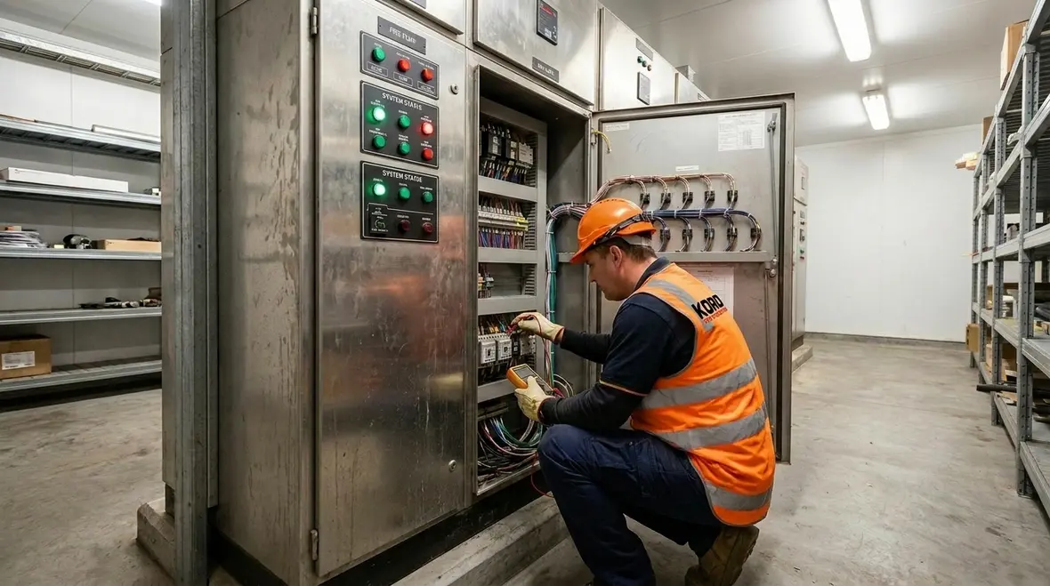
Understanding how fire pump controllers fail
Most faults fall into a few buckets: power delivery issues, input signal problems, control circuit faults, motor protection trips, or output switching failures. Even though each site has its own setup, the logic usually stays consistent. First, the controller receives a start command. Then it powers the correct output stage, checks permissives like pressure switch or run permissive, and finally commands the motor starter or VFD output. If any link breaks, the controller either refuses to run or trips to protect the motor.
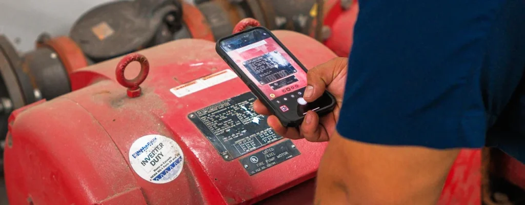
In practice, controllers often teach technicians what went wrong. A typical alarm code or LED pattern can point to a specific chain. However, technicians still need to confirm with measurements, because codes can be misleading when wiring has been changed, terminals loosened, or a sensing device drifts over time. Teams that want a deeper design-side view can also review Kord Fire Protection’s article on essential fire pump electrical requirements and design to better understand how the controller logic is supposed to behave before it starts acting like a mystery novel.
Where faults usually show themselves first
The first clue is rarely the final clue. A failed start may actually begin with a bad permissive, a weak control transformer, or a protection input that never reset. That is why technicians should follow the sequence from command to output instead of staring at one alarm and hoping it confesses. Electrical faults are not usually shy, but they are very good at sending attention to the wrong place.
Power and incoming supply checks for reliable starts
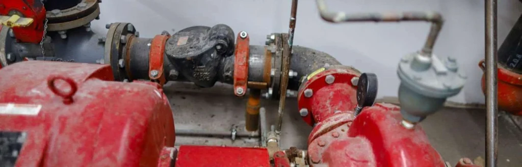
When a fire pump will not start, the first suspects are often the simplest: loss of supply, missing phases, wrong terminal wiring, or internal fuses that quietly sacrificed themselves. Technicians should confirm incoming voltage at the controller and verify phase balance where relevant. Next, they should check protective devices feeding the control cabinet, including breakers, isolators, and any upstream relays.
Then they should move to the controller’s internal power conversion path. Many units use auxiliary transformers or power supplies to feed control logic and contactor coils. If the auxiliary supply is low, the controller can behave like it is confused but not fully dead. As a result, it may show partial lights, log errors, or drop out after a brief attempt to start.
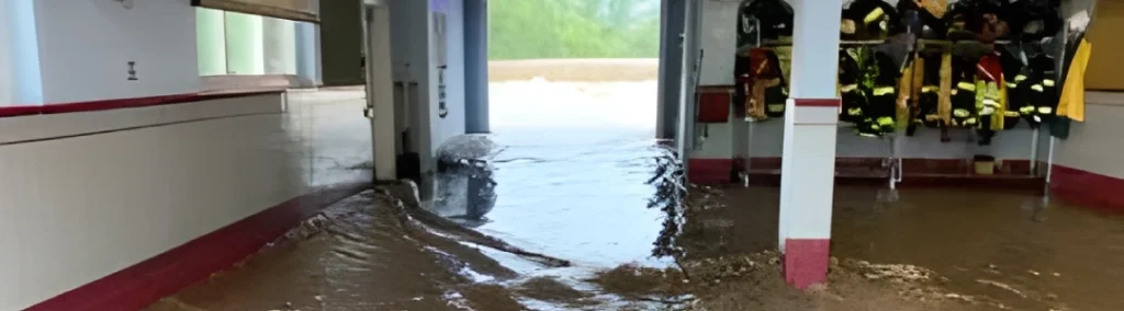
Common symptoms include repeated restart attempts, an immediate fault after pressing manual start, and intermittent power indicators. In those cases, the inspection should include terminal torque checks, inspection for heat marks on busbars and lugs, and visual checks for moisture ingress. And yes, water and electronics still do not get along. They never did, even before social media made it a trend.
A practical order for supply testing
- Verify the controller has the correct incoming voltage.
- Confirm no phase is missing or badly imbalanced.
- Inspect upstream breakers, isolators, and protective devices.
- Check internal fuses, auxiliary transformers, and low-voltage supplies.
- Look for heat marks, loosened terminations, and signs of moisture.
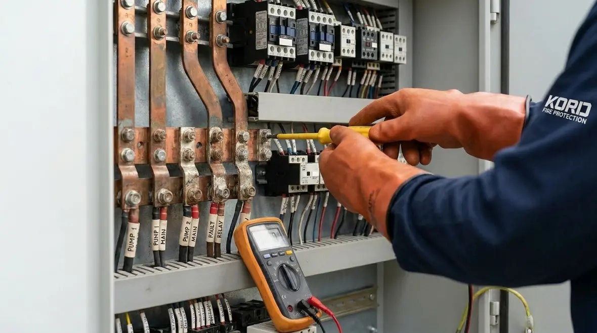
How to spot wiring and contactor coil faults
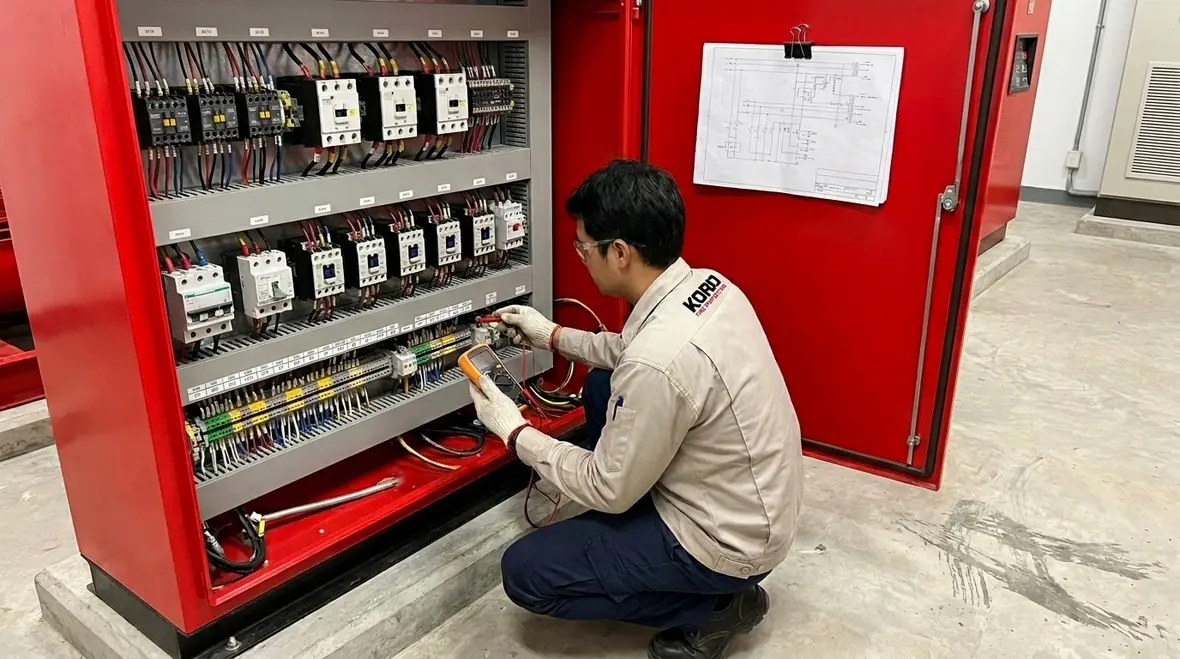
Once incoming power checks out, technicians should verify the control path. Start permissives, pressure switch signals, float switches, fire alarm interface contacts, and run enable logic all feed the controller decision. If any input is stuck open or stuck closed, the controller either won’t command a start or will start when it should not.
Contactor and relay coil faults also show up often. A coil might fail, weaken, or intermittently pick up, especially when vibration, age, or corrosion has taken a toll. Technicians can confirm coil operation by checking the coil voltage when the start command is active. If the controller outputs the start command but the coil never energizes, the fault likely sits in the coil circuit, wiring, or the output driver stage.
Field tips
- Inspect contacts for pitting, burning, or uneven wear. Those signs indicate arc events and may explain why the pump hesitates before running.
- Check control wiring routing away from power cables to reduce induced noise. Long parallel runs can cause false signals, especially with older sensors.
- Verify end-of-line resistors where fitted for supervised inputs. Missing or incorrect values cause phantom faults that waste time.
This is also the stage where technicians decide whether the controller is truly failing or merely reporting that another device has failed first. That distinction matters. Replacing a healthy controller because a coil circuit went intermittent is expensive, frustrating, and the kind of story maintenance teams tell with a long stare into the distance.
Motor protection trips and sensor signal problems
Many controller faults are not truly controller faults. They are motor protection events that the controller reports back. For example, overload relays, thermal sensors, or phase failure detection can trip and lock out the controller from reattempting. Technicians should check whether the controller is showing a motor protection alarm, and then confirm motor current and sensor continuity where safe and appropriate.
Pressure and run feedback signals also drive outcomes. A pressure transducer or pressure switch stuck out of range can cause the controller to think the system cannot build pressure. Then it may delay running or keep attempting to correct. Similarly, a flow switch or auxiliary dry contact could mislead the logic and trigger interlocks.
Transitioning from signals to verification, technicians should use a structured approach: isolate which permissive failed, test the sensor at the source, then confirm the controller receives the correct state. This reduces the trial-and-error cycle that turns Fire pump electrical troubleshooting into a guessing game. Nobody wins that game, unless you count the person selling new parts.
Why sensor issues waste so much time
Because sensor faults often look logical at first. The controller sees a pressure problem, so everyone starts discussing pressure. Meanwhile, the real issue may be a loose termination, a drifting transducer, or an interlock contact that has decided retirement sounds nice. Structured verification keeps the diagnosis tied to evidence instead of optimism.
Interpreting fault codes and log data without guessing
Modern controllers often store event logs with timestamps, alarm states, and sometimes measured values. Technicians should not treat those logs like fortune cookies. Instead, they should interpret them alongside the actual physical process. For instance, a start failed event repeated every few minutes may indicate a permissive never became true, or a protection device continued to trip.
Technicians can also correlate faults with site conditions. If an event happens after maintenance, it may link to wiring changes or a sensor calibration drift. If it occurs during rain events, moisture and condensation become more likely. If it trends during seasonal load changes, temperature or voltage stability issues may contribute. That approach pairs well with Kord Fire Protection’s article on fire pump power supply reliability for commercial buildings, because power quality and controller behavior are very often part of the same conversation.
Suggested method
- Write down the exact alarm text or code as displayed at the time of failure.
- Check the sequence of events in the log. Look for the first failure point, not only the last alarm.
- Inspect field devices connected to that first failure point, especially sensors and input contacts.
- Verify any reset required conditions before concluding the controller is defective.
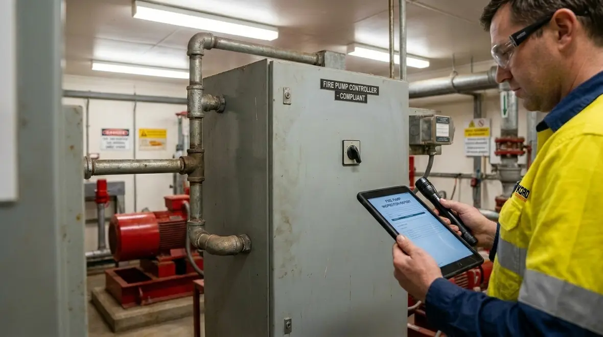
Why kord fire protection becomes a vital partner for service and compliance
On many sites, the fire pump system sits at the center of compliance planning, emergency preparedness, and operational continuity. That is where kord fire protection can become a vital partner. While technicians can diagnose many issues in-house, the broader service environment matters too: documentation quality, audit support, response scheduling, parts availability, and repeatable testing standards.
In other words, kord fire protection helps facilities move from we fixed it this time to we can prove it is reliable next time. Their broader support also connects well with fire alarm service systems when a property wants stronger coordination across life safety systems rather than treating every issue like a separate island. They support commercial, retail, and industrial facilities with service coordination, structured inspections, and troubleshooting that aligns with real operational needs across multiple sites. And yes, having a partner that keeps systems ready can save money, because emergency callouts usually cost more than planned work. Shocking, I know.
When sites work with a strong partner, they also reduce downtime risk. Instead of waiting for a single technician, facilities can align planned visits with maintenance windows. That keeps the fire pump ready while other works happen around it.

Preventing repeat faults with practical maintenance routines
After repairs, technicians should prevent recurrence with maintenance routines that target root causes. Loose terminations create heat. Heat creates resistance. Resistance creates faults. This chain is boring, but it also repeats. Therefore, planned inspections should include torque checks, contact cleaning where appropriate, verification of sensor health, and confirmation that protective devices are within expected calibration ranges.
Technicians should also check cabinet ventilation, inspect for corrosion on terminal strips, and confirm cable gland integrity to prevent water ingress. For control circuits, they should verify relay and contactor operation cycles, because fatigue can show up before complete failure. Additionally, they should confirm that firmware settings or controller configuration remains correct after any upgrades.
Finally, each site should maintain records that show tests and corrective actions. When auditors ask for proof, records should speak calmly and clearly, like a well rehearsed spokesperson. No scrambling, no panic, no uh, it worked last year.
FAQ
Call to action for reliable emergency readiness
When fire pump controllers act up, delays create risk. Facilities can reduce downtime and improve confidence by scheduling structured inspections and targeted Fire pump electrical troubleshooting. The best time to investigate a controller fault is before the next emergency gives everyone a very unpleasant reminder.
To keep your system dependable and audit ready, contact kord fire protection for a service plan that fits industrial, retail, and commercial operations. Act early, document everything, and let your fire pump system perform when it matters most.
Join Our Newsletter!
Get the latest fire safety tips delivered straight to your inbox From our Newsletter.