Reliable fire pump operation starts before the first drop of water ever moves. In the real world, the difference between “it should work” and “it does work” often comes down to essential electrical design and the way it supports the fire pump electrical requirements that code and inspectors expect. That means the power supply, controls, and protection must match the pump’s starting method, transfer behavior, and fault tolerance. In this article, Kord Fire Protection Technicians walk through how a strong design reduces nuisance trips, avoids unsafe conditions, and keeps systems ready when seconds matter. And yes, electricity can be dramatic, like a soap opera, but in a fire pump room it must stay boring, stable, and predictable.
Fire pump electrical requirements and why design choices matter
Fire pump systems do not behave like regular equipment. Therefore, the electrical design must treat the pump as a life safety asset, not a convenient appliance. When designers and contractors align the fire pump electrical requirements with the pump controller and the site power source, they prevent the most common failure patterns: voltage dips during starting, control power loss, and selective coordination failures that leave the pump without protection when it needs power the most.
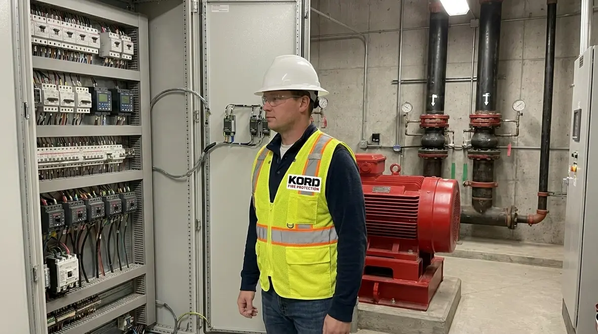
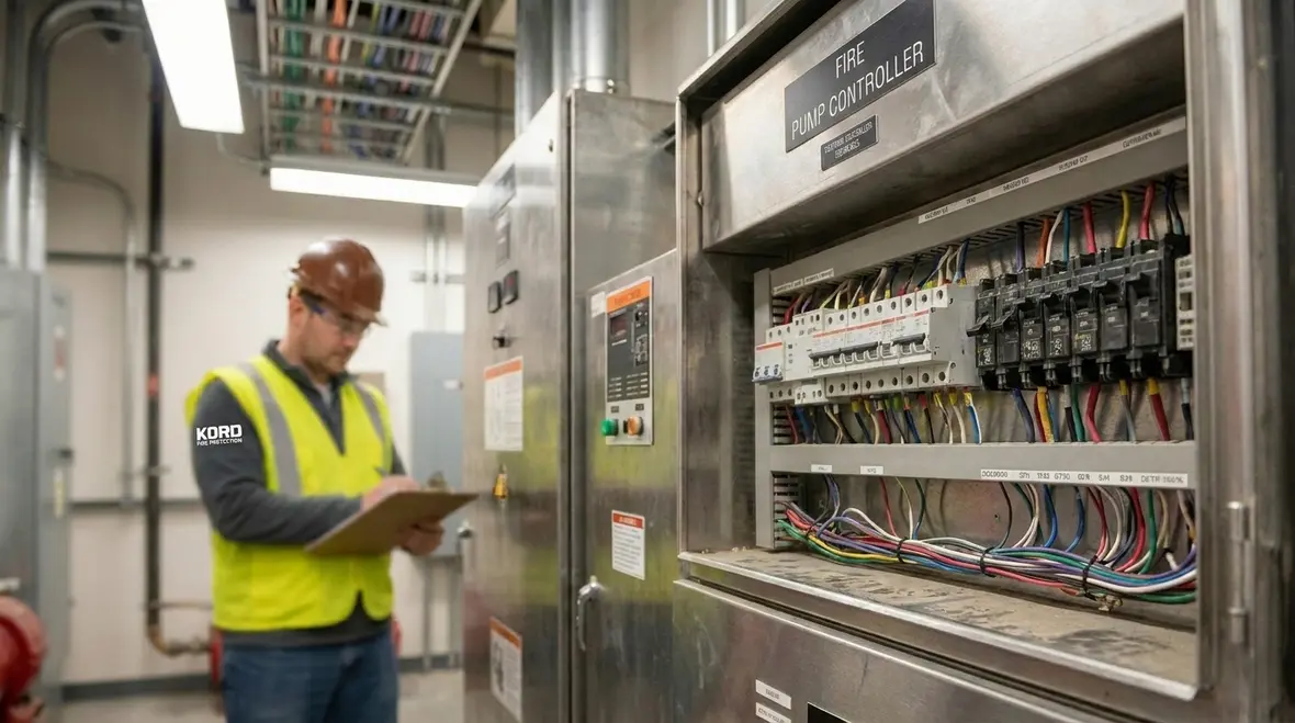
At the heart of this work sits the fire pump controller. It must receive power in a way that stays stable through starting and switching events. In addition, the controller must respond correctly to emergency signals, including pressure controller demands and any required auxiliary inputs. The goal is simple: the pump starts on command, reaches the needed speed or output, and does it without electrical drama.
As Kord Fire Protection Technicians explain, design choices influence real outcomes. A small mismatch in wiring, protective device ratings, or control voltage selection can translate into a bigger operational problem. In a fire pump room, “close enough” is not a strategy.
Power supply reliability and transfer behavior
The electrical design begins with the source of power. Most facilities rely on an engine generator, utility service, or an approved alternative. However, the transfer process must support the pump without delay or unsafe interruptions. First, the system must maintain the controller supply long enough for the pump to start and run. Then, the system must avoid momentary outages that can reset controls at the worst time.
Where transfer equipment exists, the design must account for switching time, monitoring points, and alarm behavior. Moreover, designers need to verify that protective devices and conductors can handle starting current without excessive voltage drop. If the voltage sags beyond what the controller allows, the pump may fail to start or may start in an unstable state.
Kord Fire Protection Technicians often stress documentation. When the one line diagram, the control wiring diagrams, and the device cut sheets all tell the same story, commissioning becomes easier and field troubleshooting becomes shorter. And everyone likes shorter troubleshooting, because time is money and nobody wants to babysit a relay at midnight.
Selective coordination for protection without dead ends
Protection devices exist to stop damage and reduce fire risk. Yet in a fire pump circuit, protection must never stop the pump from performing. This is where selective coordination matters. The design must coordinate upstream and downstream devices so that faults clear at the correct location while keeping the fire pump circuit available.
Instead of relying on generic settings, engineers evaluate fault currents, device curves, and conductor characteristics. They then select breakers, fuses, and any supervisory devices that will open for the right fault in the right time. If coordination fails, a downstream fault can cause a larger upstream device trip and take out the pump. That is the electrical equivalent of closing every door in the building because one window broke.
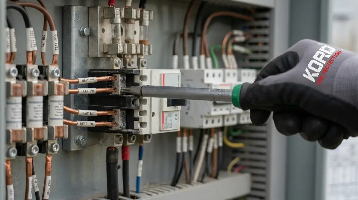
For dependable results, designers also verify equipment ratings under starting conditions. Conductors and termination points must survive heat and current pulses. In addition, the design should include proper labeling so that technicians can identify circuits quickly during inspections, service, or testing.
Control circuits, interlocks, and logic that stay true
Fire pump control systems rely on logic that must remain consistent. Therefore, the electrical design should treat interlocks and control wiring like the pump’s brain. If a relay contact fails open, if a supervision circuit misreports status, or if a wiring error reverses a polarity, the controller can interpret the situation wrong.
Common control components include pressure switch inputs, flow switch inputs, remote start signals, and status outputs for alarm and monitoring. Additionally, the controller must support automatic start under loss of pressure, and manual start during testing or emergency demand. The design must ensure that auxiliary contacts and supervision circuits match the controller’s required voltage and signaling type.
Kord Fire Protection Technicians advise teams to verify control logic during commissioning, not just on paper. They recommend functional testing that confirms each interlock behaves as intended. For example, designers should confirm that a fault in a noncritical circuit does not block the pump start path. Likewise, they should confirm that supervisory alarms rise when expected and clear when conditions correct.
Motor starting methods, voltage drop, and stable acceleration
Electric fire pumps often use motors with starting methods that can draw high current. Consequently, the electrical design must address the starting strategy and its effect on the rest of the facility. Whether the motor uses direct-on-line starting, reduced voltage methods, or a controller-specific approach, the design must support reliable acceleration while limiting voltage drop.
Engineers should calculate voltage drop for normal operating loads and for starting current. They must also confirm conductor sizing and contactor ratings. If conductors are undersized or terminations are poor, voltage drop can rise. Then the controller may sense a condition outside allowed limits and refuse to start. In other words, the pump becomes a reluctant actor who never takes the stage.
Beyond calculations, the field needs attention to detail. Tight terminations, correct torque values, and clean contact surfaces support stable performance. Also, designers should plan for proper grounding and bonding to protect against abnormal conditions and reduce nuisance trips. Kord Fire Protection Technicians typically treat grounding as a “boring but essential” part of the job, and they are right. Boring electrical design saves lives.
Grounding, bonding, and protection of equipment integrity
Grounding and bonding protect people, equipment, and control signals. When these systems are designed well, they reduce the chance of stray voltage and help protective devices operate as intended during faults. Moreover, grounding supports consistent reference points for control electronics, which can matter for sensors, supervision circuits, and the controller’s monitoring features.
The design should specify the grounding electrode system, bonding jumpers, and equipment grounding conductors. It should also address how metallic raceways and enclosures interconnect. Then, it should require testing after installation and again after major modifications.
In fire pump rooms, environmental conditions can vary. Dust, humidity, and vibration can affect terminals over time. Therefore, the design should support accessible inspection points and clear labeling for rechecks. If technicians cannot identify what they are looking at, the best design still gets delayed by confusion.

Commissioning tests, documentation, and ongoing service readiness
Even the best design can fail if the system never gets properly tested. Commissioning verifies that installed wiring, devices, and control logic match the intended design and the approved submittals. It also checks that alarm and supervisory circuits communicate correctly to the fire alarm system and that the controller signals operate as required.
During commissioning, the team should test transfer logic, confirm start and stop behavior, and verify fault response. It is also important to check that monitoring points report status correctly. For example, the controller should indicate “ready,” “running,” and any supervisory alarm states without delays or contradictions.
Then the plan must continue into service. Electrical equipment ages. Breakers, contactors, relays, and terminals can drift in performance. As Kord Fire Protection Technicians often say, you do not wait for a fire to discover a loose connection. Instead, teams establish inspection schedules, verify voltage and current trends where applicable, and test functionality during routine maintenance.
FAQ about essential fire pump electrical design
Conclusion: get dependable fire pump power with the right team
Fire pump electrical design must stay reliable under stress, not just look correct on a plan set. When facilities apply proper power transfer, selective coordination, stable motor starting support, and carefully verified control logic, they build a system that performs when it counts. Kord Fire Protection Technicians help teams review design details, validate installation, and plan commissioning so the pump stays ready and the documentation stays clean. If you want a second set of eyes before testing, reach out to Kord Fire Protection for an electrical design and commissioning readiness review.
Prefer to start with testing requirements?
Check the practical guide on what inspections and tests need to confirm so your electrical design stays aligned with real-world operation.
Need a design and readiness review?
If you want a calmer commissioning experience and a documentation trail that matches the field, start with Kord Fire Protection. Your pump deserves boring reliability.