NFPA 52 Section 21.2 General: ASME LNG Tank Installation Overview
Quick Answer
NFPA 52 Section 21.2 provides the general framework for installing ASME LNG tanks, focusing on site readiness, tank support and placement, safety clearances, appurtenances, and verification of the tank’s listed configuration. It also ties installation practice to ongoing inspection and maintenance expectations.
Facilities working to keep documentation, readiness, and recurring service aligned can also review NFPA 52 Section 15.4: LNG Facility Maintenance Requirements for a practical look at how ongoing maintenance discipline supports LNG compliance over time.
What NFPA 52 Section 21.2 “General” actually governs
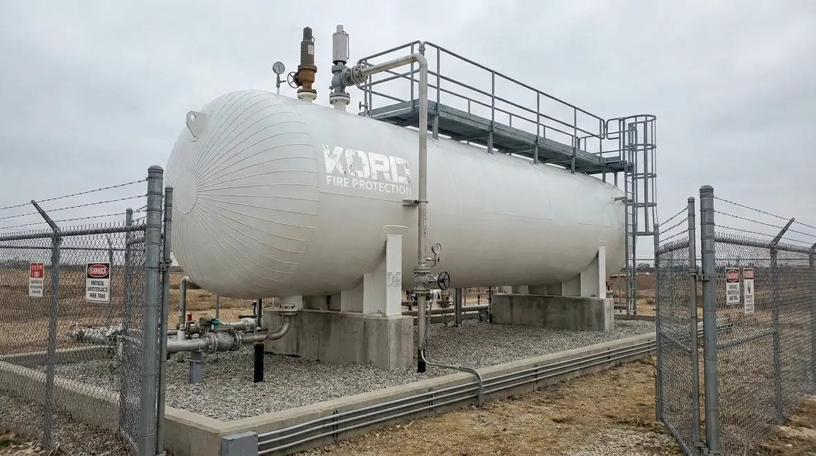
NFPA 52 Section 21.2 sets the baseline expectations for ASME LNG tank installations. While it does not replace detailed requirements found in other sections, it drives the compliance outcome: the LNG tank system must be installed as a coherent, verified safety configuration. This includes how the tank is positioned, how interfaces and appurtenances are connected, and how the installed condition aligns with the listing, the design basis, and the operational intent.
For facilities seeking NFPA 52 ASME LNG tank installation general compliance, the practical risk is not just a missing component. It is an installed arrangement that looks correct but fails the assumptions required by the safety analysis, inspection regime, and emergency operations plan.
How ASME tank listing and installation assumptions connect
Commercial LNG projects typically rely on an ASME code-compliant tank design and an engineered installation package. NFPA 52 Section 21.2 general requirements emphasize that the installed tank must remain consistent with the conditions assumed during design and certification. This matters because LNG tanks depend on integrity of cryogenic components, controlled interfaces, and correct system configuration for pressure relief, venting strategy, and heat transfer management.
Key installation linkages inspectors commonly verify
- Tank support and setting: The installation must maintain design load paths, alignment, and proper foundation performance for thermal cycling.
- Appurtenance fit and orientation: Valves, gauges, relief devices, and fittings must be installed to the intended orientation, clearance conditions, and connection specifications.
- Wiring and controls interfaces: Instrumentation and protective controls must match the expected configuration and be installed without compromising segregation, routing, or labeling.
- Penetrations and seals: Cryogenic and vapor boundary integrity depends on installation quality, correct gasket selection, and proper seal application practices.
Site and placement requirements that drive compliance outcomes
Section 21.2 general provisions influence how the entire installation is treated as a hazard-controlled system. The tank location is not a cosmetic decision. It affects credible release consequences, fire exposure patterns, access for operations and emergency response, and inspection feasibility.
Common placement and access compliance challenges
- Access for inspection and maintenance: Obstructions, insufficient clearance around valves and relief discharge paths, and inaccessible control panels can prevent required checks.
- Exposure control: Adjacent equipment, electrical infrastructure, and traffic routes must align with hazard control strategies and do not create unaccounted escalation pathways.
- Environmental and drainage considerations: Vapor accumulation risk, ignition source control, and cryogenic spill management depend on proper site grading and drainage design.
- Construction interface coordination: Changes to foundations, anchor systems, or piping routes during construction can silently invalidate assumptions if not managed under a formal change control process.
For commercial, industrial, and retail facilities, these placement issues often surface during turnover. A strong construction-to-commissioning checklist and equipment walkdown reduce rework and prevent late-stage compliance drift.
Appurtenances, piping interfaces, and mechanical integrity
In an ASME LNG tank installation, the tank is only one part of the system. NFPA 52 Section 21.2 general requirements connect tank placement with correct installation of the associated components that protect personnel, assets, and continuity of safe operation.
Mechanisms that commonly create failures
- Piping misalignment and thermal stress: Incorrect offsets or supports can lead to leaks during thermal cycling or during pressure transients.
- Improper relief and vent arrangement: Deviations in discharge routing can affect dispersion, accessibility, and compliance with venting expectations.
- Valve and gauge connection errors: Cross connection mistakes or incorrect installation of measurement devices can lead to unreliable readings and delayed detection.
- Seal and insulation installation defects: Poor insulation workmanship can increase boil off rates and create conditions that complicate safe operating envelopes.
Inspection readiness built into the installation process
Section 21.2 general compliance is easiest to maintain when the installation plan explicitly supports inspection activities. That means labeling, documentation, and physical access are treated as safety features, not administrative afterthoughts. A commissioning and acceptance process should verify that the installed configuration matches the approved drawings, manufacturer instructions, and the intended hazard controls.
Operational verification, inspection, and maintenance considerations
NFPA 52 Section 21.2 general provisions do not stop at installation. The installed LNG tank must remain safe through ongoing operational verification, inspection routines, and maintenance practices that preserve cryogenic performance and pressure protection.
What operational verification typically includes
- Initial functional checks: Controls, alarms, and protective systems must operate as designed before normal service.
- Leak monitoring and integrity checks: Verification of seals, joints, and interface integrity supports early detection and corrective action.
- Pressure relief system readiness: Relief and vent arrangements should be confirmed to be unobstructed and correctly configured for safe discharge conditions.
- Documentation and traceability: As built records, equipment submittals, and installation evidence support audit and recurring compliance.
Commercial facilities often face constrained shutdown windows, fast-moving operational demands, and mixed stakeholder priorities. That is why a maintenance program aligned to inspection requirements matters. Kord Fire Protection supports LNG and related fire protection readiness through practical inspection support, documentation assistance, and maintenance planning that helps teams stay consistent over time.
Teams that want a broader operational framework can also explore Full Lifecycle of Fire Protection Servicing for context on how installation, inspection, maintenance, and repairs stay connected in the real world.
Stay compliant through a disciplined document and test program
Compliance succeeds when installation evidence and ongoing testing are managed as a system. Facilities typically encounter audit issues due to incomplete turnover packages, unclear equipment labeling, or maintenance history that does not map cleanly to the inspection basis.
What strong compliance programs do differently
- Standardized acceptance checklists that reflect the intended configuration and inspection access needs.
- Change control during construction and modifications to prevent mismatches between installed conditions and approved design.
- Routine inspection scheduling that accounts for seasonal operations, thermal cycling periods, and known wear mechanisms.
- Clear ownership for valves, gauges, relief systems, and control interfaces so maintenance does not fall through gaps.
For additional guidance related to broader fire protection and safety readiness considerations that commonly intersect with LNG tank oversight, teams can review resources available through Kord Fire Protection. Start with Kord Fire Protection for support planning and compliance readiness coordination.
Frequently Asked Questions
Conclusion and next step
NFPA 52 Section 21.2 general requirements shape the full life of an ASME LNG tank installation, from correct setting and interface integrity to verification that the system remains inspection ready. Facilities that treat access, documentation, and maintenance as part of the installation itself reduce downtime and compliance risk. Contact Kord Fire Protection to align your installation records and ongoing inspection planning with practical LNG safety expectations.
Join Our Newsletter!
Get the latest fire safety tips delivered straight to your inbox From our Newsletter.