NFPA 52 Section 13.5: Installing Pressure Relief Valves on Residential CNG Systems
Quick Answer
NFPA 52 Section 13.5 governs how pressure relief valves must be installed on residential CNG systems to control overpressure safely. Compliance depends on correct valve selection, proper discharge routing, correct orientation, code-aligned set pressure, and verification through inspection and maintenance.
For a closely related requirement, see residential CNG fueling appliance installation guidance, which fits naturally alongside pressure control and discharge handling decisions during project planning.
What NFPA 52 Section 13.5 requires for safe overpressure control
NFPA 52 Section 13.5 focuses on preventing hazardous overpressure conditions by ensuring pressure relief devices release gas in a controlled manner when system pressure exceeds design limits. This requirement is especially important in residential CNG applications because regulators, storage components, and piping can still experience fault conditions such as regulator malfunction, thermal expansion, or blocked flow paths.
For facility teams supporting residential deployments and mixed-use properties, the practical challenge is not only installing the device, but confirming that the entire relief pathway works reliably. This includes valve installation details, discharge direction and termination, protection from ignition sources, and ongoing inspection to avoid corrosion, plugging, or improper valve reseating.
NFPA 52 residential CNG pressure relief valve installation: core compliance checkpoints
The NFPA 52 residential CNG pressure relief valve installation is only as compliant as the complete assembly around it. Installers and property maintenance teams should treat compliance as a systems task rather than a single-component task.
1) Select the correct relief device and match set pressure to system design
Correct selection prevents both under relieving and nuisance relieving. An incorrectly rated relief valve can fail to open during a true overpressure event, or it can discharge too early, creating chronic venting conditions that degrade safety margins and raise operational risk.
Set pressure and capacity: Must align with the system’s overpressure protection strategy and expected worst-case inputs.
Valve rating: Must suit the CNG application and any environmental conditions that affect performance.
Listed equipment: Use valves and components installed within their intended listings and installation instructions.
2) Install with correct orientation, connection method, and mechanical integrity
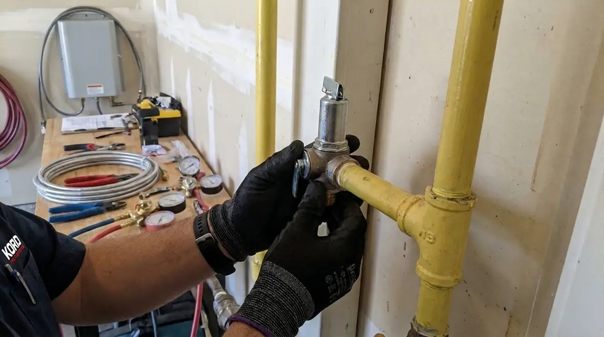
Relief valves depend on internal mechanisms that can be sensitive to misalignment and improper support. Common failures include misinstalled connections, stress on valve bodies, or damaged seating surfaces from improper handling during installation.
Orientation: Many valves require specific orientation to function as designed. Verify orientation markings and manufacturer installation directions.
Support and alignment: Provide adequate piping support so vibration and thermal cycling do not impose stress on the valve inlet or outlet.
Threading and sealing: Use approved methods and avoid sealants that can migrate into internal flow paths. Confirm the connection does not distort the valve body.
3) Route and terminate discharge to protect people, property, and ignition sources
Discharge routing is where many field installations drift from compliance because relief valve discharge can be rare and therefore overlooked. The discharge arrangement must carry vented gas away from ignition sources and avoid accumulation in enclosed or poorly ventilated areas.
Discharge direction: Must direct gas away from building openings and occupied areas.
Discharge termination: Terminations should prevent reentry and should reduce the likelihood of venting toward intake vents or doors.
Protection from damage: Protect discharge piping from physical impact and corrosion that can compromise flow and integrity.
How relief valve mechanisms fail in real-world residential deployments
Understanding failure modes improves inspection focus. Pressure relief valves typically contain a sealing element, a spring or balanced mechanism, and internal flow passages that can become impaired if the installation or operating conditions are wrong.
Common failure points
Sticking due to contamination: Particulate matter from installation debris, internal corrosion products, or moisture can prevent full lift and full reseating.
Improper discharge piping: Incorrect routing, blocked discharge, or termination placed too near building components increases hazard during discharge events.
Seating degradation from frequent cycling: Chronic nuisance relief can erode seats and lead to leakage even when the system is operating normally.
External corrosion: Corrosion can thin discharge lines or seize hardware, reducing reliability during an overpressure event.
Installation stress: Misalignment and unsupported piping can warp valve inlet geometry, affecting the internal seal and travel.
Commercial and retail facility implications
Many properties that include residential units also operate commercial and retail spaces onsite. During inspections, safety professionals should consider cross impact: a discharge outlet placed near a shared egress route, a vent termination aligned with rooftop mechanical intakes, or discharge routing that crosses fire department access pathways.
Inspection and maintenance routines that preserve code-aligned performance
NFPA 52 requires that pressure relief protection remains effective. In practice, that means inspection planning, documentation, and corrective action when performance indicators are present.
Inspection focus areas during compliance visits
Visual verification: Check discharge piping for damage, corrosion, improper supports, or blockage. Confirm routing relative to openings, ignition sources, and ventilation equipment.
Condition of valve exterior: Look for leaks at connections, coating damage, or signs of tampering.
System indicators: Review trends for regulator performance and any history of nuisance relief events or odor complaints.
Documentation: Maintain records of installation information, valve identification, and service history.
Maintenance and testing considerations
Maintenance should follow the valve manufacturer’s instructions and the system safety plan. If the facility has experienced relief events, the system and valve should be evaluated to determine root cause, not only to restore operation.
For commercial, industrial, and retail owners managing multiple properties, coordinated schedules matter. Kord Fire Protection supports ongoing compliance through inspection planning, documentation, and maintenance support for gas safety protective systems.
For a related maintenance perspective, see maintenance and inspection of nonresidential CNG appliances, which complements long-term verification planning for mixed-use property portfolios.
Installation best practices that reduce inspection findings
Field experience shows that installation details drive most compliance outcomes. The following best practices help reduce recurring inspection findings in residential CNG installations located within larger property portfolios.
Before installation
Review approved design: Confirm relief set pressure targets, discharge locations, and piping routes match the approved plan.
Verify equipment data plates: Ensure valve model, ratings, and any required accessories match the system needs.
Control debris: Prevent particulate contamination by managing worksite cleanliness and capping openings during install.
During installation
Use correct torque and connection practice: Follow manufacturer instructions to avoid distortion.
Support discharge piping: Avoid loads on the valve outlet. Ensure vibration resistance and stable alignment.
Confirm discharge termination: Validate separation from building openings, mechanical intakes, and ignition sources.
After installation
Document the as-built configuration: Capture routing, termination location, and valve identification.
Perform leak checks per approved method: Confirm no unintended leakage at connections.
Schedule verification inspections: Build a maintenance calendar so relief protection does not become a deferred risk.
Where compliance teams often miss details
Even well-installed relief valves can become noncompliant due to changes after commissioning. Compliance teams should monitor how the surrounding facility evolves.
Building renovations: New doors, windows, or rooftop mechanical units can move ignition sources and exposure points closer to discharge terminations.
Landscaping and snow management: Discharge terminations can become obstructed by plant growth, debris, or accumulation practices that were not part of the original plan.
Vehicle or equipment impacts: Physical protection gaps can lead to damage of discharge piping in mixed-use sites.
Improper repairs: Substituted fittings or unapproved discharge modifications can affect valve performance and discharge safety.
Kord Fire Protection helps owners and operators manage these real-life compliance pressures through ongoing inspection and maintenance coordination designed for commercial, industrial, and retail environments.
Frequently Asked Questions
Call to action
Ensure your residential CNG relief protection stays code-aligned and reliable by validating installation details, discharge routing, and ongoing inspection readiness. Contact Kord Fire Protection to support compliance-focused reviews, maintenance planning, and documentation for gas safety protective systems across commercial, industrial, and retail properties. Early verification reduces downtime, avoids repeat findings, and strengthens readiness for inspections and real-world overpressure scenarios.
Join Our Newsletter!
Get the latest fire safety tips delivered straight to your inbox From our Newsletter.