NFPA 25C Chapter 13: Complete Guide to Valve Inspection and Maintenance
Quick Answer
Nvinspection and maintenance of valves under NFPA 25C Chapter 13 focus on ensuring valves, valve components, and trim operate as intended. The process verifies correct position, condition, and flow path integrity, and it identifies common failure points such as corrosion, seized stems, damaged seals, and misconfigured trim.
Why NFPA 25C Chapter 13 Valve Maintenance Matters in Real Facilities
In commercial, industrial, and retail facilities, valves act as the control points that determine whether water-based fire protection systems deliver water when required. NFPA 25C Chapter 13 sets expectations for inspection and maintenance so valves and their trim remain reliable throughout service life. In practice, most valve failures do not present as dramatic mechanical breakdowns. Instead, they present as delayed operation, restricted flow, incomplete travel, or incorrect valve alignment after routine maintenance, renovation, or seasonal building operations.
Maintenance teams often struggle with three compliance challenges: (1) locating and verifying every required control and check valve on complex systems, (2) proving that trim, indicators, and auxiliary devices function correctly, and (3) documenting results in a way that supports audit readiness. A structured NFPA 25C Chapter 13 program also supports coordination with sprinkler, standpipe, and water supply system workflows.
For facilities that want a practical service path near the top of the process, fire sprinkler services and repair support can help connect inspection findings with actual system maintenance work. For a broader understanding of system installation and how valve locations fit into the overall system, refer to NFPA 13 overview for automatic fire sprinkler system installation. For ongoing water-based maintenance breakdowns that align with how valves are handled across system components, see NFPA 25 overview: complete water-based fire protection systems maintenance breakdown.
What NFPA 25C Chapter 13 Covers: Valves, Valve Components, and Trim
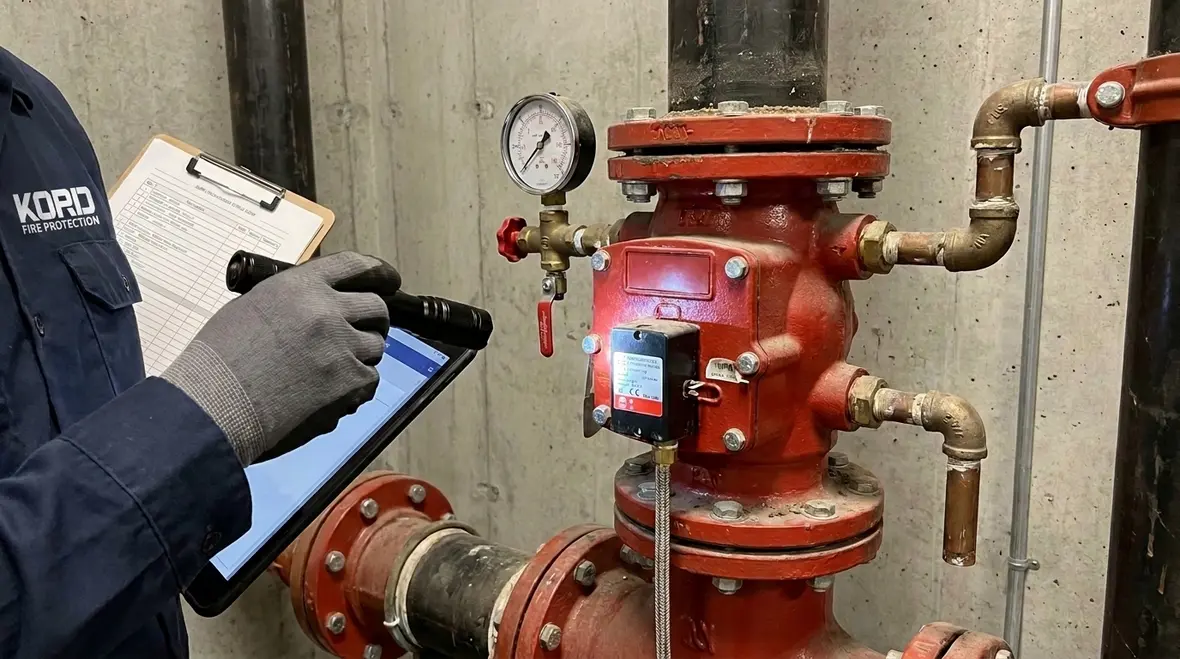
NFPA 25C Chapter 13 valve programs focus on more than the main valve body. Facilities must maintain the full valve assembly and its trim, because trim often includes the parts that ensure correct operation, indication, and safe control of water flow.
Typical valve components inspected under a Chapter 13 approach
- Valve body and ends: corrosion, scaling, dents, and damage to threads or flanges.
- Stem and seating surfaces: wear, galling, and evidence of incomplete seating.
- Handwheel or operator mechanisms: free movement, proper engagement, and integrity of hardware.
- Gaskets and packing: leaks, degradation, and packing set from thermal cycling.
- Indicators and supervisory devices: correct alignment with valve position, tamper integrity, and signal reliability where applicable.
Trim and accessories that often cause operational failures
- Drain and test connections: blockage, missing caps, damaged handles, and improper drain routing.
- Relief or pressure control trim (where provided): misconfiguration or stuck components.
- Check and control trim arrangements: restrictions that prevent proper sequence operation.
- Supervisory switches and tamper switches: misalignment after maintenance, vibration wear, or conduit damage.
When valve components trim inspection maintenance procedures ignore trim, facilities commonly discover issues only during extended commissioning or when a system must operate under emergency conditions. A Chapter 13 program reduces those surprises by treating the entire assembly as one operational unit.
Step by Step: How Valve Inspection Works (and What Inspectors Must Prove)
A strong inspection under NFPA 25C Chapter 13 begins with correct identification and ends with defensible documentation. Inspectors must demonstrate that valves remain in the required normal condition and that they respond correctly when tested, as applicable to the system design.
1) Establish the inventory and identify each valve’s duty
Before inspection begins, the facility must confirm the valve list is complete. That list should include control valves, check valves, post indicator valves or supervisory valves, and any local control or auxiliary shutoffs tied to fire protection operation. If the facility has multiple floors, multiple risers, or tenant spaces with shared plumbing, the valve inventory must cover each unique system segment.
2) Confirm valve position and inspect for physical impairment
Inspectors verify the valve position matches the system intent. They also inspect for conditions that can prevent operation, including corrosion on stems, water intrusion into valve enclosures, damaged handwheels, loose hardware, and obstacles that block access.
Common commercial failures include valves that look intact but cannot operate due to hidden mechanical binding caused by moisture, poor lubrication, or sediment on internal seating surfaces.
3) Evaluate valve condition and leak indicators
Valve inspections focus on leak evidence around packing, flange joints, and trim connections. Even small leakage can indicate worn packing or improper seating. For supervisory systems, the inspector also verifies that indicators remain consistent with the valve’s actual position and that tamper indications remain secure.
4) Verify trim integrity and configuration
Valve components trim inspection maintenance must include confirmation that all trim parts exist, are correctly assembled, and remain accessible. Inspectors check drains are present, capped as required, routed safely, and not restricted. For test headers and relief trim configurations, inspectors verify that no fittings were altered during renovations or equipment upgrades.
Maintenance Actions That Prevent Repeat Failures
After inspection, NFPA 25C Chapter 13 maintenance should focus on restoring reliability, not just correcting visible defects. Maintenance must address the root cause of failure points, especially seizure, seating problems, and trim malfunction.
1) Free movement and stem lubrication strategy
Valves that require mechanical operation for testing or functional verification can become stiff when stems accumulate corrosion and sediment. Maintenance should address stem condition and ensure consistent travel without damaging seating surfaces. Where lubrication is permitted by the valve manufacturer, maintenance should use compatible lubricants and follow manufacturer guidance.
2) Seating, seal, and packing correction
When leaks or incomplete seating evidence appear, maintenance often requires packing adjustment or replacement, gasket replacement, or restoration of sealing surfaces. The goal is to restore the seal without compromising trim performance or creating a new leakage path through over-torque or incorrect packing selection.
3) Cleaning internal flow path restrictions
Sediment and corrosion products can restrict flow path performance even when a valve appears to open and close. Maintenance practices may include cleaning accessible portions of the assembly and verifying internal integrity when permitted. Any disassembly must follow manufacturer procedure and restore all components to the original configuration.
4) Restore trim alignment and supervisory device reliability
After repairs, trim components must be returned to the designed arrangement. Inspectors should verify that position indicators and supervisory switches report correct valve state. In facilities with frequent construction activity, misalignment after patching or ceiling work is a recurring problem.
Kord Fire Protection supports this work through field-ready procedures designed for commercial valve systems where documentation, repeatability, and audit support matter. For facilities needing alignment across code expectations for water-based protection maintenance, Kord Fire Protection also supports broader system compliance planning through their maintenance breakdown resources at NFPA 25 overview: complete water-based fire protection systems maintenance breakdown.
Common Valve Failure Points Found During Chapter 13 Inspections
Chapter 13 programs repeatedly identify the same operational weaknesses across facility types. These issues can appear gradually and then lead to sudden loss of reliability.
Seized or restricted operation
Corrosion at the stem, sediment buildup, and lack of free movement can prevent full travel. Even when a valve is “in the correct position,” seized movement can prevent corrective action when needed during emergency operations or functional testing.
Damaged seals, packing wear, and flanged joint leaks
Worn packing and degraded gaskets cause leaks that can lead to water damage, loss of readiness, and early deterioration of trim and mounting hardware.
Improper trim connections or missing components
Missing caps, altered drain routing, blocked test points, and missing handles create an inability to safely test or drain as required.
Incorrect indicator alignment and supervisory reporting issues
Inspectors frequently find that indicators or switches report valve state incorrectly after maintenance, replacement, or minor mechanical adjustments. This can create a false “normal” condition, delaying response.
Access and physical impairment
In retail and mixed-use buildings, storage obstructions and restricted access keep personnel from verifying valve position quickly. NFPA 25C Chapter 13 readiness depends on valves being inspectable and maintainable under normal operating conditions.
Implementation Best Practices for Commercial Compliance
To make NFPA 25C Chapter 13 valves valve components trim inspection maintenance effective and sustainable, facilities should standardize how they manage documentation, access, and repair verification.
Build a maintenance workflow that matches facility realities
- Assign valve ownership by system zone and riser so each area gets consistent coverage.
- Plan inspections during low-traffic windows to avoid blocked access issues.
- Use photo documentation to show valve position, trim integrity, and access pathways.
Maintain traceable repair verification
After service, the facility should verify normal position returns, trim components operate as intended, and supervisory indicators match actual valve state. Traceable verification reduces repeat findings and improves audit defense.
Integrate ongoing code awareness for local compliance alignment
Local amendments and interpretations can affect documentation expectations and system operating constraints. For state-level context that many facilities request when managing sprinkler and water-based systems, see fire sprinkler code California explained. For additional industry context on fire protection system performance and related infrastructure, facilities also reference firepumps.org when coordinating water supply, pumping, and system reliability programs.
Kord Fire Protection and KordFire teams support ongoing compliance through structured service planning. If a facility operates across regions, consider coordinating with local service coverage such as kordfire.com.au and aligned technical support channels.
Frequently Asked Questions
Call to Action
Ensure NFPA 25C Chapter 13 valve readiness with a complete valve inspection and maintenance program covering valve components and trim. Kord Fire Protection can help commercial facilities build an audit-ready maintenance workflow, correct recurring failure points, and verify supervisory and trim performance. Schedule a compliance review so the facility can confirm every valve and trim assembly is functioning correctly and documented for ongoing risk reduction.

Join Our Newsletter!
Get the latest fire safety tips delivered straight to your inbox From our Newsletter.