NFPA 20 Main Relief Valve Centrifugal Pump Protection
Quick Answer
NFPA 20 main relief valve centrifugal pump protection keeps industrial fire systems safe by releasing excess pressure in the pump discharge. Section 4.20 guides siting sizing and testing to prevent water hammer and pump damage. Across Australian facilities this valve ensures reliability and uptime. Kord Fire Protection can become a vital partner by delivering design installation and ongoing maintenance with local expertise.
For broader context on fire pump compliance, it helps to review how NFPA 20 regulates fire pump systems. If your site needs coordinated support beyond one component, full fire protection services can fit naturally into planning, installation, and maintenance workflows.
Introduction to NFPA 20 Section 4.20
In fire protection systems the NFPA 20 main relief valve centrifugal pump plays a pivotal role. Section 4.20 of NFPA 20 addresses the main relief valves that protect centrifugal fire pumps from overpressure during start up and shutdown or rapid flow changes. The main relief valve acts as a safety path for excess water when the system demands exceed what the pump can deliver. Correct siting sizing and testing are essential to keep the pump and piping intact while providing dependable extinguishing performance. In short this valve keeps the system calm while the world around it raises the volume.
Why Main Relief Valves Matter for Industrial Facilities
Industrial retail and commercial facilities rely on steady water supply for fire protection. When a centrifugal pump starts or stops the chances of pressure spikes rise. The main relief valve is the shield that prevents damage to pumps and piping and reduces water hammer risk. With proper relief valve operation facilities experience less unscheduled downtime fewer nuisance alarms and more predictable performance during emergencies. In many ways it is the quiet guardian of a loud system.
Sizing and Installation Essentials
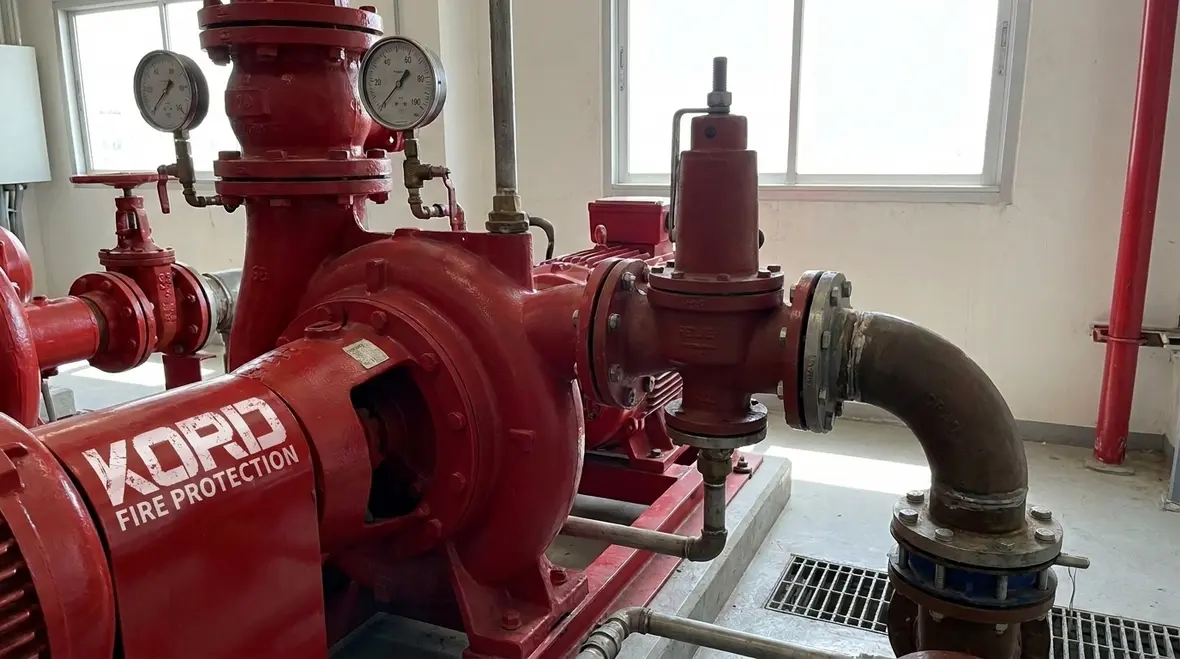
Proper sizing means the relief valve must handle the maximum potential discharge while remaining closed during normal operation. The valve should be installed on the pump discharge side and connected to a safe vent or drain. Piping geometry matters a lot both for venting and for avoiding back pressure that could cause nuisance opening. Controls and instrumentation should clearly indicate when the valve opens and the system should be inspected for any blockages or leaks. When done well the relief valve becomes a dependable partner in the fire protection network.
Key details that deserve attention
- Valve location on the pump discharge should be confirmed against the design intent.
- Set pressure should match the system requirements rather than someone’s best guess on a busy day.
- Drain and vent routing should avoid unsafe discharge conditions.
- Instrumentation should make valve operation visible during testing and troubleshooting.
Kord Fire Protection as a Trusted Partner
Kord Fire Protection brings a wealth of experience across industrial facilities retail locations and commercial campuses. They offer design build and ongoing maintenance services ensuring NFPA 20 4 20 compliance and reliable operation of the main relief valve centrifugal pump. The team coordinates testing inspections and retrofits with a focus on minimal downtime and clear communication. With Kord Fire Protection on the project teams you gain a partner who speaks your language whether you are assembling a new facility or upgrading an aging system. In short they can be a vital ally delivering steady protection with a calm professional tone even when the pressure is on.
Maintenance and Testing Practices
Maintenance matters every day in the field of fire protection. Regular testing ensures the main relief valve functions as intended and that the setting remains appropriate for the system. Routine inspections look for corrosion leaks and proper actuation. Records of tests and adjustments should be kept and reviewed during system audits. While NFPA 25 governs water based fire protection system testing the relief valve discipline under NFPA 20 ensures a consistent baseline for reliability and safety across facilities in Australia and beyond.
Two Column Quick Reference
- Confirm valve location on the pump discharge
- Verify correct set pressure according to system design
- Ensure venting to a safe location
- Inspect for leaks and corrosion during every maintenance window
- Document test results and any adjustments
- Coordinate with building management and authorities having jurisdiction
- Schedule regular training for operators
- Plan spare parts and quick replacement strategies
- Assess impact of retrofits on existing piping and valves
- Include a maintenance forecast in the facility budget
Applications Across Australia Industries
Australian facilities in manufacturing mining hospitals retail complexes and commercial campuses benefit from a robust relief valve strategy. The approach stays practical across diverse climates and building codes. Local teams adapt NFPA 20 principles to align with AS/NZS requirements while keeping the system resilient under peak demand. The result is a fire protection backbone that remains steady whether the warehouse floor hum of equipment or the hiss of a sprinkler system fills the air. Kord Fire Protection supports these efforts with on site expertise and practical solutions.
Frequently Asked Questions
Conclusion
Protecting a centrifugal fire pump with a well designed main relief valve is a smart steady move for any facility. By aligning with NFPA 20 Section 4.20 and partnering with Kord Fire Protection facilities gain a trusted ally for safe reliable protection. Reach out today for a site assessment and a plan that fits your operation.

Join Our Newsletter!
Get the latest fire safety tips delivered straight to your inbox From our Newsletter.