NFPA 20 Fire Pump Controller Location and Starting Requirements
Quick Answer: NFPA 20 Sections 10.2-10.5 spell out where the fire pump controller goes, what it must be built from, which parts it includes, and how it must start. Done right, it keeps pumps reliable when seconds matter. Kord Fire Protection can coordinate design, installation, testing, and handover so compliance and uptime land together.
In Australia’s industrial, retail, and commercial facilities, fire pump performance cannot rely on “close enough.” Within the first moments of an alarm, NFPA 20 lays out the fire pump controller location and the starting requirements that help ensure the system responds the way the code intends. NFPA 20 Sections 10.2 through 10.5 go deeper than a checklist. They address where the controller sits, how it is constructed, which components it must include, and how it initiates pump operation. After that, the real work begins: building and maintaining a system that keeps working in dusty plant rooms, busy retail back-of-house corridors, and facilities where people do not always treat safety gear like fine china.
For facilities that want practical help beyond the paper requirements, Kord Fire Protection also supports broader fire alarm monitoring systems that improve visibility when life safety events demand fast action, and teams can also review how NFPA 20 regulates fire pump systems for wider context around the standard’s intent.
Fire pump controller location: why placement controls reliability
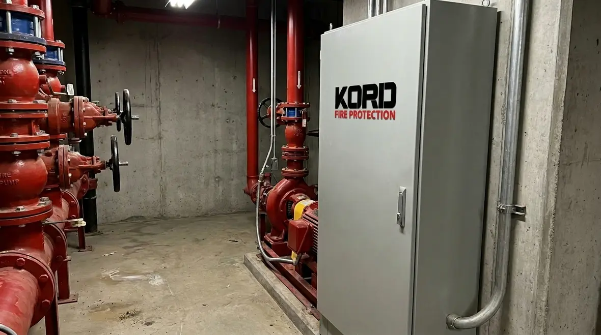
The fire pump controller location requirements in NFPA 20 focus on keeping controls accessible, protected, and ready for immediate use. Therefore, the controller must be installed in a location that supports dependable operation and practical maintenance. It should be near the pump equipment it controls, yet positioned so technicians can inspect, test, and troubleshoot without crawling through a maze of pipe insulation and bad decisions.
Next, the environment matters. Moisture, dust, heat, and physical damage can degrade electrical components over time. So the controller should be placed where it does not take unnecessary abuse. For many facilities across Australia, that means selecting a dedicated space with controlled conditions, proper clearances, and protection from impacts. If the controller ends up somewhere convenient instead of suitable, the code will still be correct, but performance might not be. And that is the kind of comedy no one wants during a real event.
To support the rest of the system, placement also affects wiring runs and electrical noise exposure. Longer runs can introduce more opportunities for faults. Consequently, careful route planning protects both function and future testing. It also makes future inspection far less painful, because nobody enjoys tracing critical control wiring through a room that looks like three contractors made decisions in a blackout.
What good placement solves before startup day
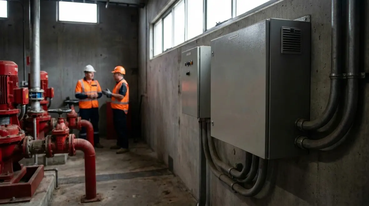
A smart location solves more than compliance. It gives maintenance staff room to work safely, reduces the chance of accidental bumps or water exposure, and shortens the path between diagnosis and fix when a fault shows up. In busy commercial properties, that matters because pump rooms rarely stay pristine. They collect storage temptations, stray tools, and the occasional “temporary” item that mysteriously gets a long-term lease. The controller should not have to share its working space with that kind of chaos.
Controller construction and enclosure: built to survive the real world
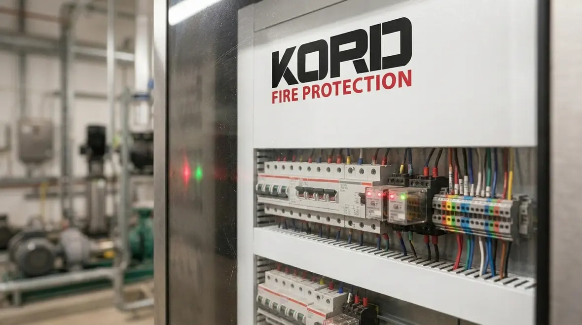
NFPA 20 Section 10.3 addresses construction of the fire pump controller, with a clear goal: reliability under fire conditions and during normal life. The enclosure and assembly must provide protection for internal components, while still supporting required access for inspections and servicing. In facilities where plant rooms run hot and dirty, or where retail service corridors see constant foot traffic, robust construction helps the controller maintain integrity.
Additionally, the controller must withstand expected operating conditions. That includes vibration and possible temperature swings. Therefore, proper materials, secure mounting, and sound workmanship are not optional extras. They are part of the compliance foundation that reduces nuisance issues and prevents failures that only show up after the test schedule has ended.
Kord Fire Protection works with clients to confirm the controller’s physical location and environmental fit, then aligns installation practices to those realities. In other words, they keep the controller from becoming a “temporary” installation that somehow lasts ten years. You know the one. The one held together with optimism and a hope-and-pray checklist.
Why enclosure quality matters after installation
A controller can pass inspection day and still struggle later if its enclosure is not suited to the space around it. Dust intrusion, loose door hardware, inadequate mounting, and poorly protected internal wiring all chip away at long-term reliability. Strong enclosure selection helps preserve the control logic, power components, and status indication that operators depend on. It is not glamorous, but neither is discovering that a cheap cabinet choice became the most expensive shortcut in the room.
Components in NFPA 20 Section 10.4: the parts that must be there
NFPA 20 Section 10.4 requires specific components within the controller so the system performs as designed. These components manage power, control signals, protection, and indication. Therefore, the controller does not just “start a pump.” It coordinates the sequence the pump needs to come online safely and effectively.
- Power and control circuits that support reliable operation
- Switchgear and protective devices that guard against electrical faults
- Control logic and interfaces that respond to fire alarm inputs
- Monitoring and indication to show status during normal operation and tests
- Field wiring terminals and interlocks that connect the controller to the pump and alarm system
As a result, the controller becomes the control hub. If any required piece is missing, incorrectly wired, or poorly labeled, the system may behave like it is haunted: it works until the one time you need it. And that is not a thrill ride you want for emergency life safety.
This is also where documentation earns its keep. A complete controller is only half the story if nobody can quickly identify terminals, protective devices, or control functions during testing. Good labeling and tidy assembly reduce diagnosis time, improve maintenance quality, and make the whole setup far less dependent on whichever technician happens to remember what the original installer “probably meant.”
Component checks that prevent future confusion
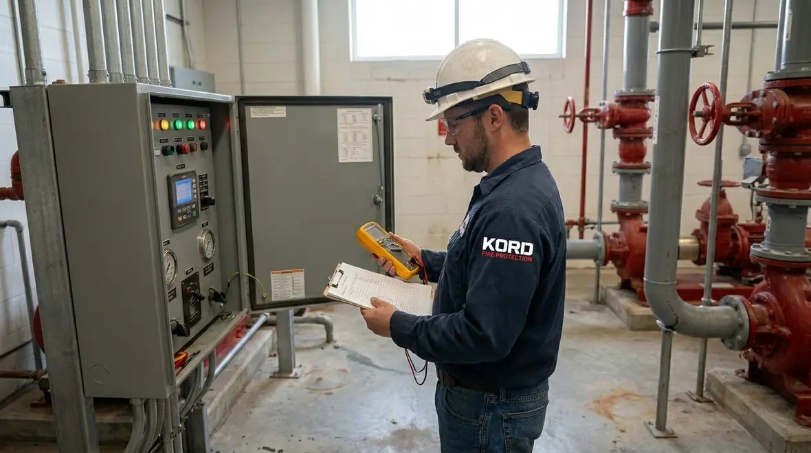
During review, teams should confirm not only that required components exist, but that they are correctly coordinated with the pump type, power arrangement, and field interfaces. A beautiful cabinet full of mismatched parts is still a problem. The goal is a controller that communicates clearly, starts reliably, and gives maintenance staff information they can trust when alarms and deadlines arrive together.
Starting requirements in NFPA 20 Section 10.5: sequence, inputs, and confirmation
NFPA 20 Section 10.5 sets starting requirements that govern how the controller initiates pump operation. In most real-world installations, starting occurs based on specific fire alarm signals and system conditions. The controller must then execute the start sequence correctly, including the right timing, correct output to the pump, and the necessary supervision so the system can confirm that it did what it should.
To deliver that behavior, the controller must be wired and configured correctly for the facility’s pump arrangement and fire alarm interface. For example, it must respond to the correct input types, maintain appropriate control logic, and provide status indication that can be verified during routine tests. Therefore, careful commissioning matters as much as the equipment itself.
Also, starting performance links directly to overall system readiness. If the controller is installed in the wrong place, protected poorly, or assembled with incomplete components, starting can fail under real conditions. Kord Fire Protection helps clients prevent that chain reaction by focusing on compliance details, practical installation, and repeatable test methods across industrial, retail, and commercial sites.
Commissioning is where the sequence proves itself
A startup sequence should never be treated like a vague promise. It needs to be proven under realistic conditions, with every input, output, alarm, and indication checked in order. That way, teams know whether the controller merely powers up or actually performs its job. The difference matters, because a controller that looks confident on the front panel can still be hiding wiring errors behind the door like a teenager hiding laundry under the bed.
Installation workflow: from plans to commissioning without the “mystery failure”
Many projects lose time and confidence in the gap between design intent and field execution. Thus, a structured workflow reduces the risk of rework and hidden defects. A strong process looks like this:
- Site verification to confirm the chosen controller space supports clear access, environmental protection, and safe cable routing
- Shop drawing and specification review to confirm the controller construction and component list match NFPA 20 requirements
- Control wiring and labeling so technicians can trace circuits quickly during inspection and tests
- Functional checkout that checks inputs, outputs, and status indication before a full system test
- Commissioning and documentation so the facility receives clear records and a workable maintenance plan
Then comes the part no one brags about at industry parties: documentation. Yet that is what helps future audits and ensures teams can repeat what works. Also, the best commissioning approach builds confidence for maintenance staff, not just the commissioning engineer.
Below, a dual view helps teams quickly understand what gets verified and what gets recorded during the process.
| Step | What gets checked |
|---|---|
| Controller location and enclosure fit | Access, protection from damage, clearances, routing quality, and environmental suitability |
| Component verification | Required functional parts, protective devices, monitoring outputs, and correct interface readiness |
| Starting sequence confirmation | Correct input response, output timing, and clear status indication after start commands |
| Recordkeeping | Test results, settings, wiring identification, and handover documentation for ongoing compliance |
Testing, maintenance, and life-cycle readiness for commercial sites
Once installed, fire pump controller performance depends on maintenance discipline. Therefore, facilities should schedule inspections that verify the controller’s condition, confirm wiring integrity, and validate that starting and indications still operate as expected. Even if the equipment “looks fine,” internal faults can develop due to heat, humidity, vibration, or loose connections.
Moreover, ongoing testing helps catch drift. Sensors can degrade. Interfaces can change if someone modifies a related panel. Labels can fade. So routine work keeps the system aligned with its original intent.
Kord Fire Protection supports clients beyond first install. They help teams maintain confidence that the controller still meets the code expectations that govern reliability. In the end, emergency equipment should not feel like a surprise episode of your favorite streaming series where nobody knows what happens next. It should behave predictably, every time.
FAQ
Final word: plan the controller with confidence, then keep it that way
NFPA 20 Sections 10.2-10.5 give a clear path for where the fire pump controller goes, how it is built, what it includes, and how it starts. However, the field details decide whether the system performs. Thoughtful layout, durable construction, complete components, and clean commissioning all work together to protect reliability when a real demand arrives.
Kord Fire Protection can partner with your team across Australia to deliver compliant installation, solid commissioning, and maintenance support that keeps your fire pump controller ready. Call now to review your project and close the gaps before they close in.

Join Our Newsletter!
Get the latest fire safety tips delivered straight to your inbox From our Newsletter.