Fire Suppression Electrical Safety Protocols in Australia
Quick Answer: During fire suppression system deployment, electrical risk can spike fast. Teams must follow fire suppression electrical safety protocols, verify power isolation, control ignition sources, and test circuits after installation. With proper planning and partner support, facilities in Australia can protect people, assets, and downtime budgets, instead of playing “guess and hope” with power.
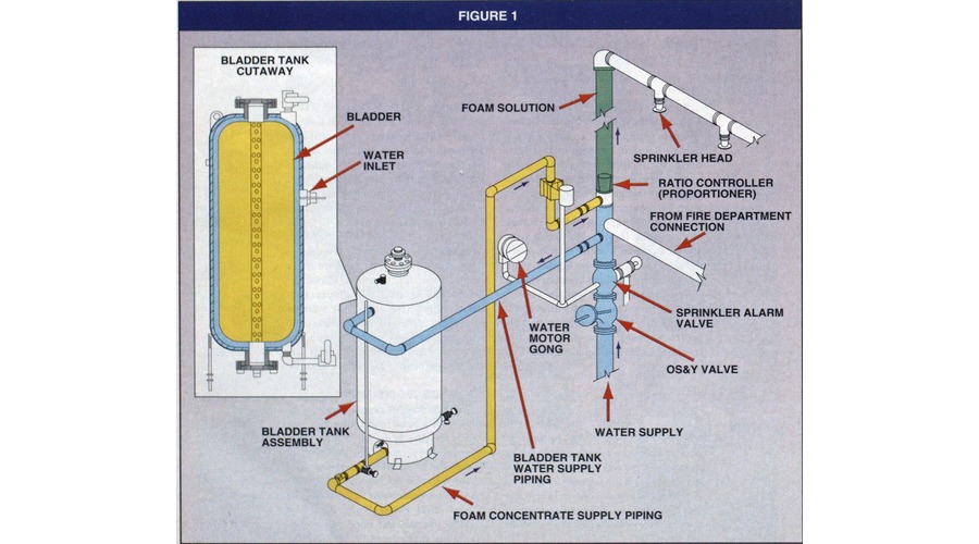
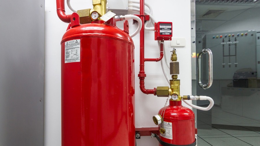
When a facility upgrades sprinklers, gas systems, foam, or clean agent equipment, electrical hazards can sneak in while technicians are running cables, adding detectors, wiring panels, and commissioning controls. That is why fire suppression electrical safety protocols need to guide the work from the first site walk through the final test and sign off. Those protocols keep energised equipment separated, reduce the chance of arc faults, and ensure suppression equipment performs as designed when it matters. And yes, electricity can be dramatic. It behaves a lot like a pop star: it looks fine until the spotlight hits, then suddenly everyone needs answers. Fortunately, a strong deployment process turns chaos into control.
For facilities needing a broader partner during planning, full fire protection services can help align suppression work, inspections, and electrical coordination before the first cable gets touched. That matters because suppression systems rarely live in isolation. They interact with alarms, interfaces, shutdown logic, and equipment that all depend on clean electrical execution.
Planning for Electrical Risk Before Any Cable Moves
Before anyone drills a single wall, a project team should map the electrical landscape and the suppression scope together. First, they should identify existing power routes, panels, and control circuits tied to alarms, shutdowns, pumps, valves, and monitoring devices. Then they should create a step-by-step installation plan that aligns with lockout, test, and commissioning timing.
In industrial, retail, and commercial facilities across Australia, the biggest mistakes usually arrive early. For example, a cable route might cross through an area where panels are energized, or a technician may temporarily bypass a safety interlock to “make the job easier.” Therefore, the plan should set rules for cable management, temporary power use, and protection of terminals from moisture, debris, and metal shavings.
Finally, coordination matters. Teams should confirm access windows with operations, fire service managers, and site electricians, because switching work during peak operations can multiply risk. Meanwhile, suppression installers should share wiring diagrams and point lists so electrical staff can prepare isolation boundaries and testing points up front. That level of preparation keeps the project from drifting into the classic category of “we thought someone else had that covered,” which is never a fun category to discover halfway through a commissioning day.
Where early planning usually saves the day
- Identifying live panels and protected zones before routing cable
- Confirming which interfaces tie into alarms, pumps, valves, and shutdown controls
- Setting temporary power rules so convenience does not create exposure
- Making sure electrical and suppression teams work from the same point list
- Reducing rework that tends to appear late, expensive, and annoyingly avoidable
How Fire Suppression Electrical Safety Protocols Reduce Shock, Arc, and Ignition
Fire suppression systems rely on sensors, control panels, solenoids, pump starts, and signaling devices. Consequently, improper electrical practices can lead to shock hazards, unintended activation, or ignition sources that worsen an incident. Proper fire suppression electrical safety protocols focus on preventing faults before they occur and verifying safe operation after the work.
Key controls typically include isolation and verification, correct grounding, and strict management of conductors during termination. In addition, technicians should use properly rated tools and test equipment to confirm insulation integrity and continuity. They should also confirm that cable types match the environment and expected load conditions, especially around pump rooms, switchboards, and areas with dust, fumes, or high humidity.
To keep the job moving without cutting corners, teams should set a “no energized crossover” rule for temporary staging. Also, they should label circuits clearly so commissioning does not turn into a scavenger hunt. Because when the panel expects one input and receives another, it is not just a wiring problem. It is a reliability problem. Kord’s related article on fire suppression electrical interface reinforces the same idea: signals, controls, and pathways have to agree with the intended sequence or the system can look ready without actually being ready.
Core controls that reduce electrical trouble
- Verified isolation before touching conductors
- Proper cable selection for heat, moisture, dust, and load conditions
- Clear circuit identification during staging and commissioning
- Grounding and bonding checks that support stable system behaviour
- Strict handling of temporary test wiring so it does not become permanent by accident
Power Isolation and Lockout for System Commissioning
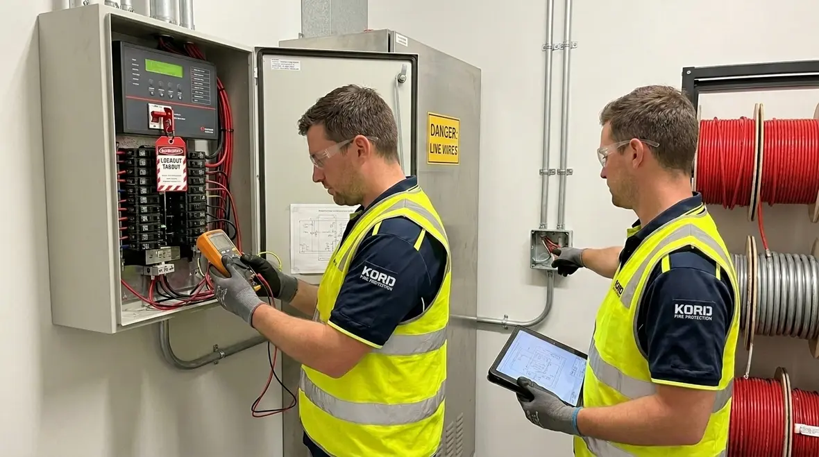
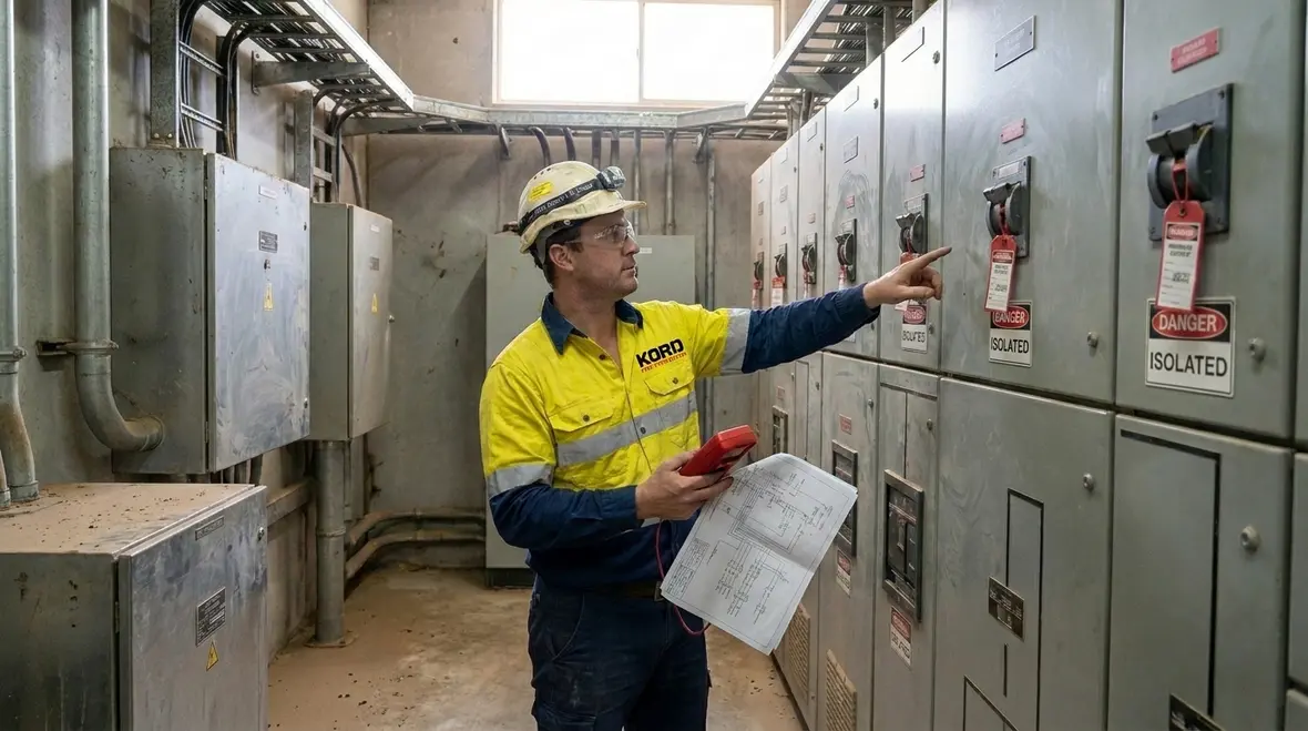
During deployment, the team often needs to energise certain circuits for testing, while keeping other circuits de-energised for safety. This is where many sites get sloppy, so the process must be disciplined and documented. First, personnel should isolate supply, lock out controls, and verify absence of voltage at the exact points of work, not just at the panel. Then they should keep lockout boundaries clear so no one restores power without authorisation.
After isolation, verification should follow a clear sequence using calibrated meters and proper test steps. Moreover, the team should ensure that suppression control circuits remain protected from backfeeding and that temporary test arrangements do not bypass safety interlocks. When suppression panels include supervised circuits, shorting, misrouting, or loose terminations can cause confusing faults that appear “random” until someone traces the entire run.
To avoid delays, the project should include a commissioning checklist that links every installation step to an electrical verification step. That way, the work does not stall at the end when everyone is tired and the meters are missing. That last part is always funny until it stops the schedule. A checklist also helps site leadership see what has been isolated, what has been tested, and what still needs controlled energisation before the system can move to acceptance.
Wiring, Earthing, and Detector Placement Without Creating New Hazards
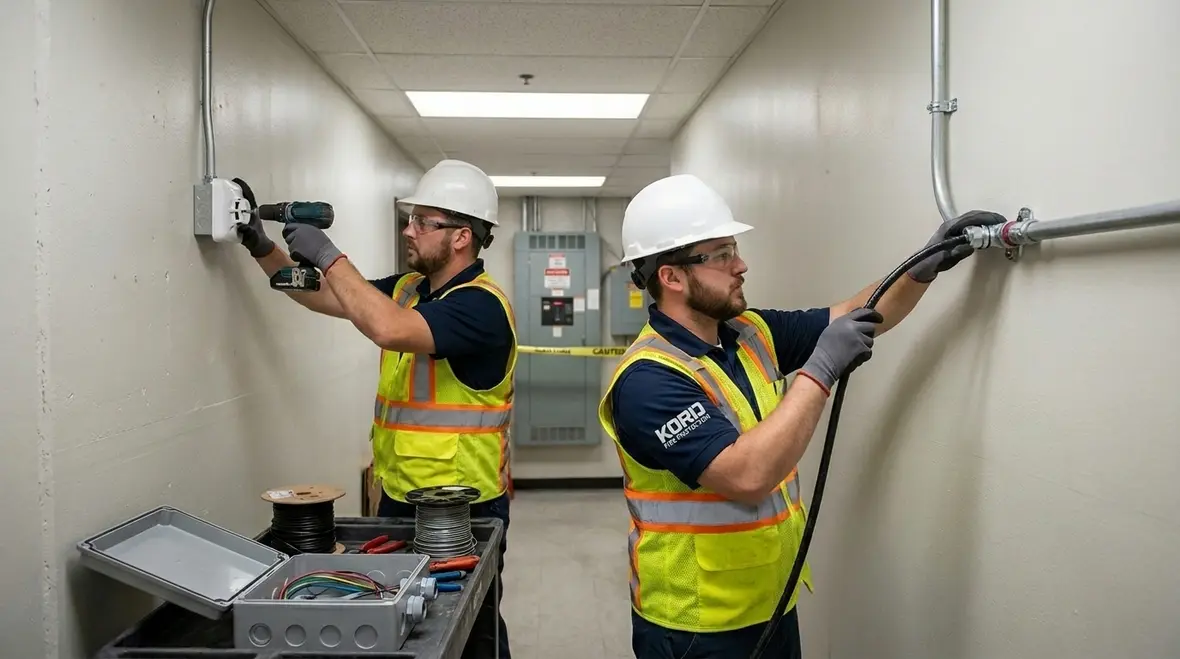
Suppression systems can include detection devices, release panels, and interface wiring to HVAC controls, door releases, and emergency signalling. Accordingly, wiring quality determines both safety and system response time. Technicians should route cables to prevent abrasion, avoid sharp edges, and protect from mechanical damage. They should also use correct cable glands and seals, especially in wet or corrosive zones.
Earthing and bonding deserve special attention. A weak earth connection can lead to nuisance faults, degraded sensing performance, or dangerous conditions during fault events. Therefore, the team should check terminations, verify bond continuity, and confirm that metal enclosures and cable screens tie into the intended earthing scheme.
Detector placement also influences electrical risk. For instance, relocating detectors to suit layout without updating wiring runs may cause extension or ad hoc connections. Instead, the project should keep the detection plan consistent, and update wiring diagrams when design changes happen. Then, technicians should test each circuit as installed rather than waiting for final acceptance.
In short, good workmanship stays visible. It shows in neat terminations, correct torque, clean labeling, and stable system behaviour during functional testing. It also shows in what does not happen: no mystery faults, no strange supervision errors, and no one staring at a panel like it personally betrayed them.
Workmanship details that matter more than people think
- Protected cable runs with no sharp-edge exposure
- Sealed entries that match wet, dusty, or corrosive conditions
- Consistent detector layouts tied to updated drawings
- Verified earth and bond continuity across metal enclosures
- Clean, torqued, labeled terminations that make future testing easier
Testing and Documentation After Installation: Proving Safety, Not Just Claiming It
After mounting suppression hardware and completing wiring, the team should run electrical acceptance tests that align with the facility’s requirements and system design. They should verify insulation resistance, continuity, polarity where relevant, and correct response of circuits to supervisory conditions. Then they should confirm that alarm and release outputs operate under controlled functional tests.
Furthermore, commissioning should include checking interface points such as pump start circuits, valve actuator control, and shutdown relays tied to plant equipment. If the job modifies emergency power behaviour or interacts with fire-alarm panels, the team should test those interactions carefully. Otherwise, the facility may experience unexpected shutdowns or, worse, missed actions during a real emergency.
Documentation should not be an afterthought. The team should record as-built wiring, test results, and any change notices. That documentation helps future maintenance, speeds troubleshooting, and supports compliance audits. It also saves time for the next contractor who arrives, looks at the panel, and asks, “Who wired this?” Less drama is always a win. For facilities expanding broader coverage, related guidance on special hazard fire suppression in Australia can also help frame how installation quality, commissioning, and long-term readiness fit together.
Why Kord Fire Protection Can Be a Vital Partner for Safe Deployments
For many sites, electrical safety becomes the deciding factor between a smooth installation and a stretched timeline filled with rework. That is where Kord Fire Protection can become a vital partner. They bring a deployment mindset that values coordination, risk controls, and practical on-site execution. Instead of treating suppression work as a standalone task, they align the system installation with electrical boundaries, testing needs, and commissioning expectations.
As projects move across industrial, retail, and commercial facilities throughout Australia, the value of a consistent partner grows. Kord Fire Protection can help teams plan cable routing impacts, manage system documentation, and maintain clear handover steps so electrical staff and suppression technicians stay on the same page. Consequently, the facility avoids mismatched scope assumptions and reduces the chance that electrical safety gaps appear at the finish line.
In business terms, this protects uptime, reduces call-backs, and keeps the site leadership confident. And in safety terms, it reinforces the discipline behind fire suppression electrical safety protocols across the full job lifecycle. That same whole-system mindset also shows up across Kord’s broader Australia fire protection guidance, where readiness depends on planning, evidence, and follow-through instead of crossed fingers and optimistic paperwork.
FAQ About Electrical Safety During Fire Suppression System Deployment
Next Steps: Request a Safety-Led Deployment Plan
Facilities that plan early avoid delays, rework, and safety gaps. Kord Fire Protection helps teams coordinate suppression installation with electrical risk controls, so commissioning stays predictable and documentation stays clean. If a site is scheduling upgrades for detectors, panels, pumps, or release systems, now is the time to align scopes and testing steps.
Reach out to map the job plan, confirm isolation requirements, and secure a safer deployment path. A disciplined process protects people, assets, and operating continuity, while giving everyone involved far fewer reasons to play the wildly unpopular game of “guess and hope” with live power.

Join Our Newsletter!
Get the latest fire safety tips delivered straight to your inbox From our Newsletter.