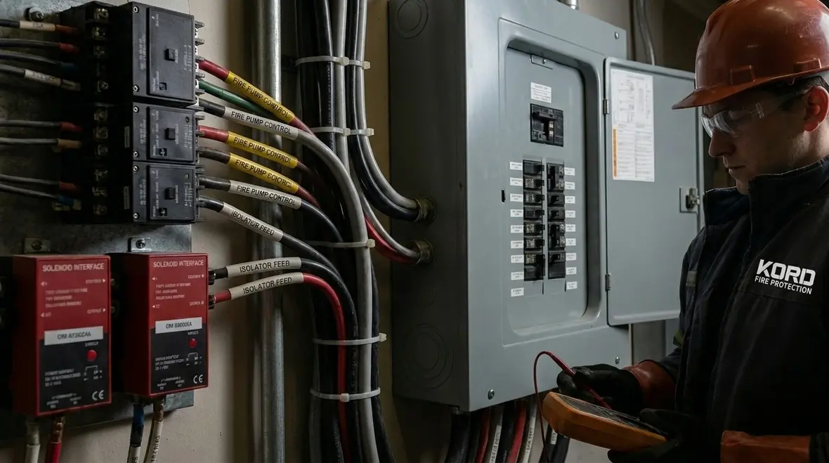
The fire suppression electrical interface keeps control signals reliable
Electrical integration starts with how information travels through the system. Sensors detect smoke, heat, or flame, and then they must send a clear signal to the control unit. The fire suppression electrical interface helps move those signals safely into the right circuits for initiation, notification, and monitoring. Without that coordination, the system can lose time, confuse states, or fail to communicate.
For example, when a sprinkler system needs to trigger pumps, valves, or releasing devices, the control logic must match the building’s design. Therefore, integration engineers and kord fire protection technicians verify that the system’s electrical pathways align with the intended sequence. They also confirm that voltage levels and contact types fit the equipment requirements. In plain terms, the system cannot “guess” what a command means. It needs a signal that actually means something.
How wiring, power, and control devices work together
Fire suppression systems rarely rely on power alone. Instead, they use a mix of power paths, control logic, and feedback circuits. Consequently, electrical integration ties together three common layers.
1) Power distribution ensures the right equipment receives the right supply, with correct grounding and protection methods.
2) Control pathways carry commands from the control panel to devices such as pump starters, solenoids, and release mechanisms.
3) Supervision and feedback monitor device status so operators can confirm the system stands ready, not “kinda ready.”
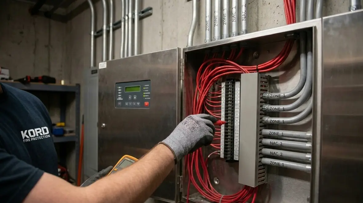
Now, the fun part, meaning the part no one wants to do twice: wiring must follow the system design and the installation standards. If a terminal is labeled for normally open operation but the field wiring is reversed, the system may still power up, but it may not perform correctly during an alarm. Additionally, the system can report trouble conditions that waste response time.
That is why kord fire protection technicians pay close attention to circuit identification, wire routing, labeling, and termination quality. They treat the electrical system like a map. If the map has a crooked street name, the fire department will still arrive, but they will take the long way. And nobody wants that.

Why signal supervision prevents false starts and blind spots
A modern system does not only act. It also watches. Supervision provides visibility, so operators know whether devices respond as expected. When integration includes proper supervision, the control panel can detect open circuits, short circuits, and device faults before an actual fire event.
Consider the alarm initiating devices and releasing circuits. Supervisory wiring monitors that circuits remain intact. If someone accidentally dislodges a terminal or if a cable gets damaged during renovations, supervision can flag trouble conditions. Then the facility team can fix the issue before the building needs protection.
Therefore, supervision also supports consistent behavior during high stress moments. During an event, the system should not hesitate or report contradictory statuses. Instead, it should communicate clearly: which zone initiated, which device released, and whether pumps or valves activated.
Just like a GPS that keeps updating, supervision reduces uncertainty. It keeps the system from “thinking” it did something when it actually did nothing. And if that sounds dramatic, well, so does a silent failure.
Mechanical action depends on correct electrical sequences
Electrical integration controls timing and coordination for mechanical components. Yet the mechanical side must also receive the right electrical triggers. For example, releasing panels, solenoid valves, and pump systems often require specific sequencing. If the control sequence triggers components out of order, the system might delay activation or cause improper operation.
So, the integration design must reflect the physical system design. Kord fire protection technicians often review the required sequence steps, including activation delays, interlocks, and any required confirmation feedback. Then they verify wiring routes and control contact behavior.
One common challenge involves pump and valve control. Pump starters can draw significant current, and the control system must trigger them with the proper interface. Also, the system must not overwhelm circuits or violate equipment limitations. That is where proper design and careful electrical installation matter. When those details get ignored, the system can behave like a stubborn employee who “tries” but never follows policy.
As a result, integration testing becomes essential. Technicians confirm that commands lead to intended outcomes, and they document verified sequences so future service teams can maintain the setup with confidence.
Installation standards and testing that kord fire protection technicians follow
Field work can look like simple cabling, but it involves disciplined methods. Kord fire protection technicians treat installation quality as part of the system performance. That means they follow accepted installation practices for cable type, routing, separation, and termination.
They also handle commissioning steps that prove the system behaves correctly. Testing can include checking circuit continuity, verifying device responses, and confirming panel reporting. Furthermore, they simulate initiating events in controlled ways to observe release and monitoring behavior. They review logs and trouble histories so the system does not hide problems behind “temporary” errors.
Because systems live in real buildings, they also consider service access and future changes. Cable paths and interface points should support ongoing inspection and troubleshooting. Otherwise, maintenance teams end up performing contortions with flashlights and hope.
In addition, technicians check that the electrical integration supports emergency conditions. That includes power reliability, grounding integrity, and correct operation of standby power where applicable.
Electrical integration also supports monitoring, reporting, and compliance
Fire suppression systems do not serve only the moment of activation. They also support ongoing monitoring for safety teams and compliance requirements. When electrical integration uses the right interface approach, the control panel can provide status signals for supervisory monitoring, alarm events, and device condition reports.
This improves response planning. Facilities teams can see trouble conditions early and schedule repairs. Maintenance teams can also use event history to understand patterns, such as nuisance faults from a specific zone or repeated wiring issues after tenant improvements.
Moreover, clear monitoring and reporting supports coordination with building management systems and, where required, with alarm communication pathways. That means fewer handoffs and fewer “I thought you had that” moments. People still make those mistakes, of course, but the system should not.
When kord fire protection technicians explain compliance readiness, they often emphasize that good electrical integration produces clear documentation and stable performance. In business terms, it reduces risk, reduces downtime, and helps teams stay ahead of inspection findings.
Real world scenarios where integration makes or breaks performance
It helps to see how electrical integration behaves during real conditions. Buildings change. Tenants remodel. Engineers add equipment. During all that activity, electrical details can get overlooked. Here are a few examples where integration matters most.
- Renovations near device locations can damage wiring or disconnect terminations. Supervision and clear labeling help detect faults early.
- Complex mechanical interlocks require correct control logic so valves and pumps activate in the intended order.
- Multiple zones with shared control modules need accurate circuit mapping so the system initiates the correct area.
- Power fluctuations or grounding issues can create erratic behavior. Strong integration design reduces those risks.
| Integration focus | What it prevents |
|---|---|
| Proper interface wiring and terminals | Misrouted signals and incorrect device states |
| Supervision of circuits | Open or short circuits going unnoticed |
| Correct sequencing and interlocks | Delayed or out of order mechanical action |
| Testing and commissioning | Hidden wiring errors that show up only during emergencies |
FAQ about electrical integration in fire suppression
Conclusion: upgrade confidence with the right electrical integration
When a fire suppression system matters, electrical integration matters more. It keeps signals reliable, supervision active, and mechanical action correctly sequenced. Kord fire protection technicians help facilities protect what they own by verifying wiring, testing behavior, and supporting clear monitoring and reporting. If your system uses older interfaces or needs updated commissioning, now is the time to address it. Contact qualified professionals to review your electrical integration and strengthen performance before the next inspection season arrives.
Next step: If you are also planning water-based system commissioning and ongoing verification, review Kord Fire’s Fire Pump Testing Requirements: Things To Know for practical testing expectations.
Know Your Weapon Before You Fight the Flame
Kord Fire Protection is your go-to when it comes to all things fire protection. For over 20 years, we’ve been serving Southern California with the quality service and equipment to keep your home or business safe at all times. Our competitive prices reflect our unwavering commitment to protecting what matters most in the event of a fire emergency. Give us a call, send an email, or use that form!
Join Our Newsletter!
Get the latest fire safety tips delivered straight to your inbox From our Newsletter.