Fire Pump Controller Troubleshooting Steps for Commercial Sites
When a fire pump controller acts up, commercial facilities cannot afford guesswork. That is why fire pump controller troubleshooting starts with a calm, step by step plan that keeps systems safe and downtime short. In the real world, kord fire protection technicians have seen everything from nuisance alarms to pumps that refuse to start, and they know the difference between a real fault and a “sounds scary but isn’t” situation. In this guide, third person readers will get essential steps that help facility teams diagnose problems quickly, verify correct operation, and document fixes the right way. And yes, sometimes the controller is like a pop quiz from hell, but it still follows rules.
Confirm the controller symptoms and safe operating status
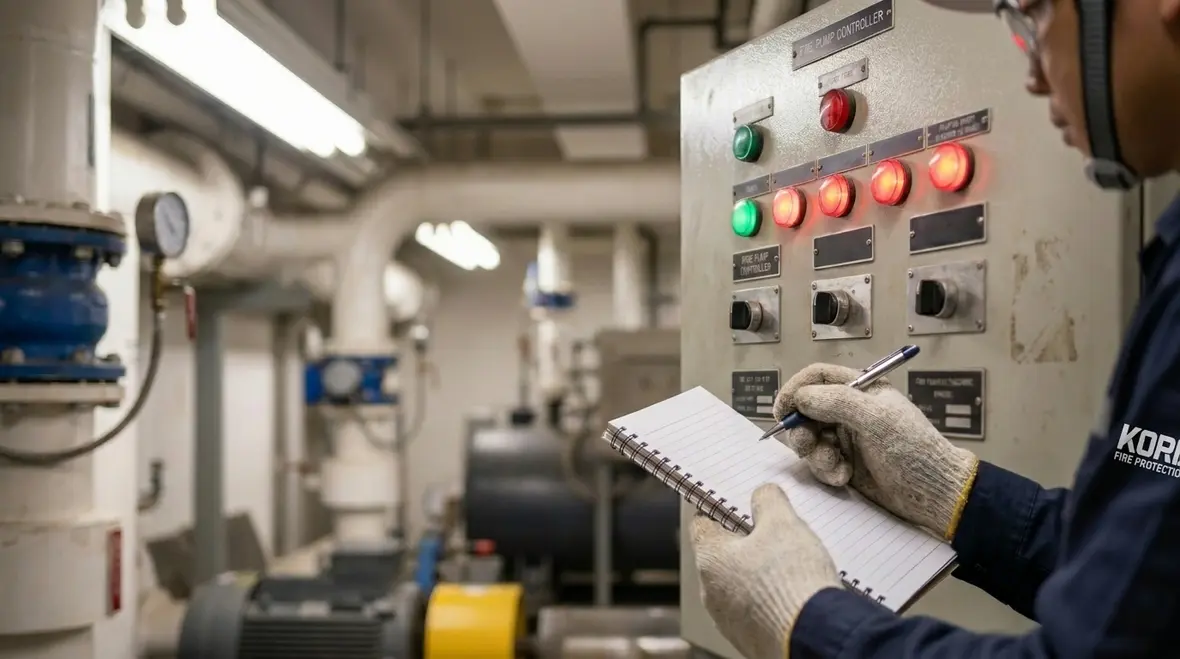
Before anyone touches settings, technicians confirm what the controller is doing. First, they note whether the issue is a start failure, an alarm message, a voltage or phase fault, or a fault that clears and returns later. Then they check if the controller indicates automatic mode, whether remote signals exist, and whether the pump circuit breaker is in the correct position. While it feels obvious, many cases start with basic observations that teams skip when they are in a rush. Those first five minutes often decide whether the rest of the troubleshooting goes smoothly or turns into a frustrating loop of second guessing.
Next, kord fire protection technicians verify that conditions match the expected sequence. For example, when a demand signal occurs, the controller should respond in a predictable time window. If the pump never tries to start, the fault path usually points to control power, permissives, or interlocks rather than a random mechanical issue. And if the pump tries to start but drops out, that often signals load problems or wiring faults. This is where discipline matters, because skipping straight to assumptions wastes time and can even create new issues.
Inspect power, wiring, and controller communications
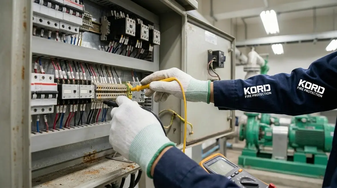
Reliable troubleshooting begins with power checks. Technicians verify incoming power to the controller, check control transformer output, and confirm correct fusing. After that, they inspect terminal blocks for looseness, look for signs of heat, and confirm cable runs are seated properly. If corrosion exists, technicians clean and retighten connections, then recheck the controller behavior after power normalization. These small fixes are surprisingly common and often resolve issues that look much bigger at first glance.
Next, they review any network or monitoring connections if the controller supports supervisory communication. Many modern sites push alerts to building automation or monitoring panels, and a stale status can cause confusion. Therefore, technicians compare controller history logs with what the building system shows. If the controller reports a fault that the monitoring system does not display, teams can isolate whether the issue lies in the controller, the I O modules, or the reporting path. In complex facilities, this step can save hours by narrowing the problem to a single communication layer.
For deeper understanding of pump systems and components, teams often reference resources like fire pump systems and components to ensure every part of the system is working together properly. Troubleshooting is not just about fixing what is broken, but understanding how each piece interacts under real demand conditions.
Verify sensors, permissives, and interlocks
Controllers do not run pumps blindly. They wait for permissives such as pressure switch status, flow switch status, tank level signals, fire alarm interface demand, and phase or motor protection signals. So technicians test those inputs one by one. They confirm that pressure transducers read reasonable values and that switch contacts close and open as expected during simulated conditions. This step ensures the controller is not being “lied to” by bad data.
Also, they check for interlocks that block pump start. For instance, a controller may lock out due to an active fault, a lockout relay, or an “off” mode selected by a local panel. While facility staff may assume everything is in auto, the controller can show a different truth. Therefore, kord fire protection technicians often start by verifying mode selection, controller reset settings, and any manual inhibit flags. These small switches can completely change system behavior.
To keep the process organized, they write down each permissive status and the exact controller response after changes. That record later helps engineering teams avoid repeating the same test like it is a scene from a sitcom where nobody remembers the rules. Over time, these records also build a history that helps predict recurring issues before they escalate.
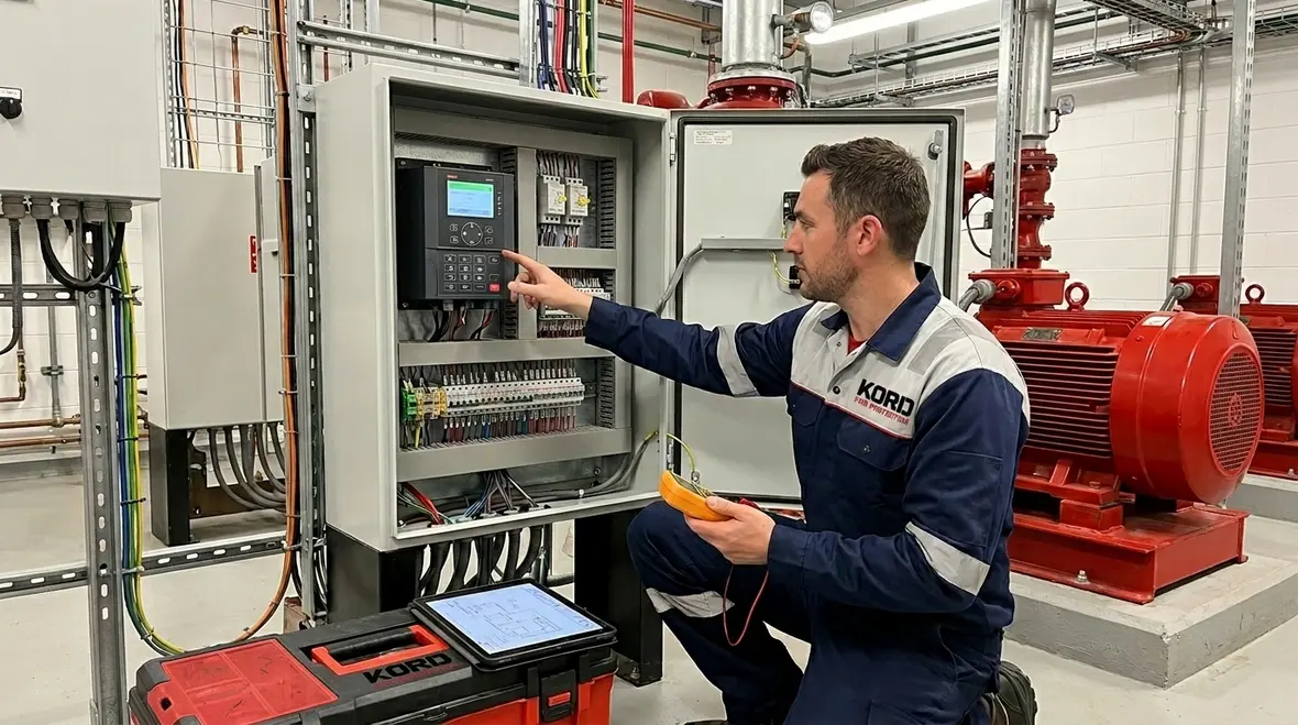
Check motor starter outputs and motor protection
Once inputs and permissions make sense, technicians confirm the controller outputs. They inspect whether the controller energizes relays, starter contactors, or variable frequency drive commands. Then they verify that overload contacts and motor protection relays do not stop the motor prematurely. This is where electrical troubleshooting becomes more detailed and requires careful measurement.
If a pump fails during starting, the controller usually records an event like “start attempt” followed by a fault. Therefore, technicians correlate that log entry with electrical measurements. They check motor circuit voltage, confirm correct phase, and verify that starter auxiliary contacts return to the right state. If a controller attempts to start but never sees “running” feedback, that often points to a feedback wiring issue or a faulty auxiliary contact. These signals are critical for confirming the pump is actually operating.
Additionally, they confirm that any soft starter or VFD parameters match the motor and pump load. Incorrect ramp settings can cause nuisance trips. And while it sounds like a technical detail, it often explains why a pump behaves fine during a quick test but fails when the system demand lasts longer. Consistency under real load is what ultimately matters.
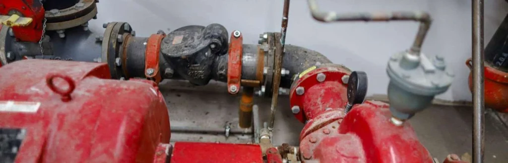
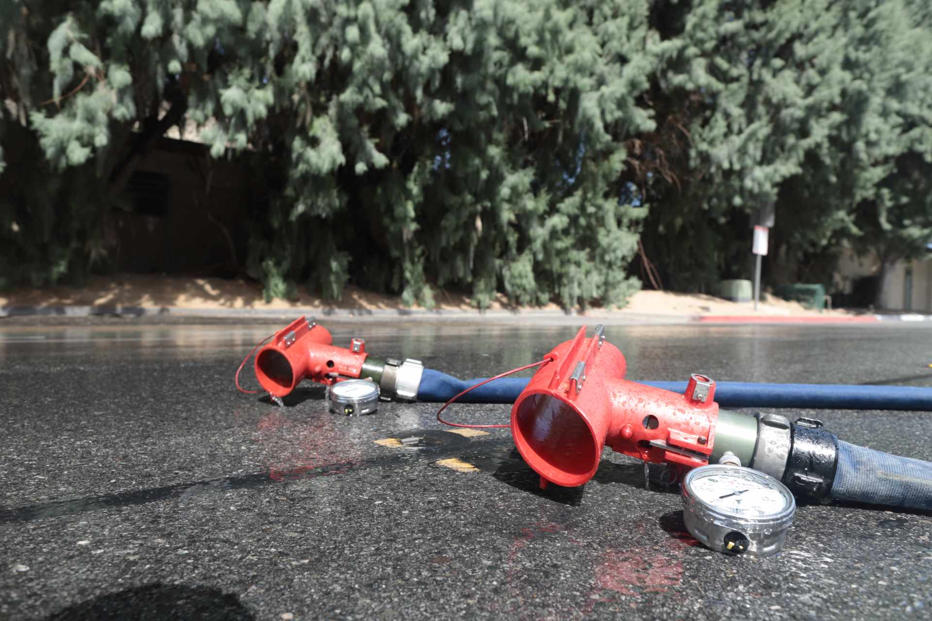
Assess pump performance signals and pressure behavior
After electrical checks, troubleshooting shifts to the system side. Technicians verify pressure readings from gauges, pressure switches, and the controller’s transducer. Then they compare the expected performance during discharge to the actual response. If pressure drops quickly or fails to rise, it may indicate a blocked discharge, closed valve, air in the suction line, or a pump that does not reach speed. These clues help separate control issues from hydraulic problems.
Meanwhile, technicians check for signs of improper priming or suction issues. In some facilities, the system has a history of intermittent problems that line up with changing seasonal water conditions. So they observe whether the controller behaves differently across different test times. Transitioning from “will it start” to “how well does it pump” helps isolate whether the issue lives in control logic or in pump hydraulics.
When technicians correct a problem, they confirm results using the required test method for the jurisdiction and the facility’s fire protection plan. In other words, they do not just celebrate the controller silence. They confirm the pressure and flow behavior match the design intent and ensure compliance with safety standards.
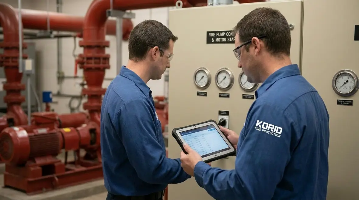
Document findings, confirm repairs, and run a verification test
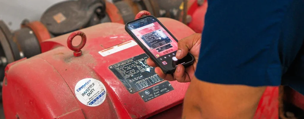
Solid troubleshooting ends with proof. Kord fire protection technicians typically document the symptoms, the fault codes, the measurements taken, and the exact changes made. Then they run a verification test that validates normal operation and safe fault recovery. After repairs, they confirm the controller can start the pump in the correct sequence, clear alarms properly, and return to monitoring without new lockouts.
To keep teams aligned, they use a simple checklist and often keep the controller log screenshot or printed record in the maintenance file. This documentation becomes a powerful reference for future troubleshooting and ensures consistency across teams.
FAQ: fire pump controller troubleshooting quick answers
Next steps for commercial teams: get it right, faster
Fire pump controllers should not be treated like a guessing game, and they should never wait until a later inspection to receive attention. Facilities that follow structured troubleshooting steps reduce downtime and improve reliability. From verifying power and inputs to confirming outputs and pump behavior, each step builds toward a clear answer instead of a risky assumption.
If this is an active issue at your site, consider working with professionals who specialize in fire pump systems and diagnostics. Experienced technicians can evaluate the controller, validate the full sequence, and ensure the system performs when it matters most.
Join Our Newsletter!
Get the latest fire safety tips delivered straight to your inbox From our Newsletter.