NFPA 31 Section 10.2: Basic Requirements for Installing Oil Burners
Quick Answer: NFPA 31 Section 10.2 sets the minimum installation expectations for oil burners so they operate safely, reliably, and in compliance with protection, piping, wiring, and ventilation requirements. The section focuses on correct burner placement, controls, fuel connections, and safe startup and shutdown conditions in commercial settings.
For teams looking at broader installation discipline and code-focused planning, Kord Fire Protection’s comprehensive fire protection system design guidance is a useful related resource near the start of the process, especially when burner work overlaps with mechanical room safety, documentation, and inspection readiness.
What does NFPA 31 Section 10.2 cover for oil burner installations?
NFPA 31 governs the safe installation, operation, and maintenance of oil burning equipment. Section 10.2 addresses NFPA 31 oil burner basic installation requirements by establishing baseline expectations for the physical installation and the immediate integration of the burner with the boiler or furnace, including how the burner interfaces with fuel supply piping, electrical controls, combustion air, and safeguarding components. In commercial, industrial, and retail facilities, these baseline requirements directly impact reliability, inspection readiness, and the ability to maintain safe combustion conditions over time.
For facilities under continuous demand, the most common compliance failures do not involve exotic scenarios. They involve missing or altered components, poor fuel line routing, incorrect electrical interface practices, degraded seals, or installation details that prevent proper combustion adjustment and verification.
Section 10.2 installation fundamentals: where burners must be correctly set up
Basic installation requirements in NFPA 31 Section 10.2 center on ensuring the burner is installed to support safe ignition, stable combustion, and proper control operation. Installers typically focus on the “hardware” outcomes, such as secure mounting and correct alignment, but the inspection outcomes depend on functional relationships between components.
1) Proper burner mounting and integration with the appliance
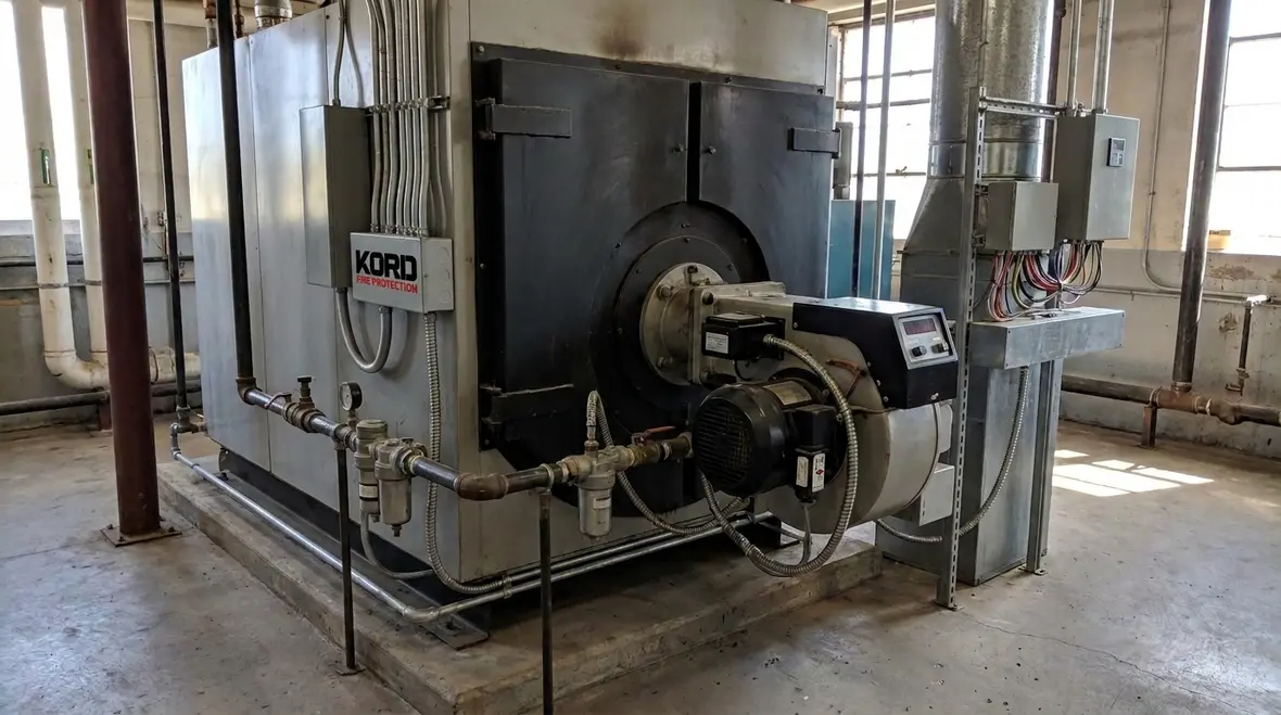
A burner must be mounted so it seats correctly on the boiler or furnace and supports proper combustion configuration. Misalignment can create localized air and fuel distribution problems that surface as soot, odor complaints, or unstable flame characteristics during commissioning and periodic service. Commercial maintenance teams should plan for consistent access paths to service the burner, controls, and filters without compromising safety.
2) Control and safeguard interfacing must remain intact
Oil burner systems rely on interlocked controls and safeguards to enforce safe ignition sequence logic and shut down unsafe conditions. Installation practices must preserve the intended control topology, including wiring integrity, correct sensor placement, and correct termination of components used to prove flame and limit unsafe states. A recurring operational risk is “temporary” wiring changes that remain in place after troubleshooting.
3) Combustion air and ventilation must support stable operation
Even when Section 10.2 addresses basic installation requirements, it connects directly to the combustion environment. If combustion air provisions do not support complete combustion, the burner can produce excessive smoke, carbon monoxide, or particulate matter. In occupied commercial spaces, this can trigger indoor air quality issues and repeated service cycles that never resolve because ventilation assumptions are incorrect.
Fuel oil piping and connections: the compliance details that fail first
Fuel oil piping details often create the gap between “installed” and “compliant and serviceable.” NFPA 31 installation expectations require that piping and connections support safe fuel delivery and allow correct operation of burner components such as filters and fuel pumps.
1) Routing, support, and leak prevention
Fuel piping must remain mechanically supported and protected from damage. Poor routing can cause abrasion, restrict flow, or allow vibration transfer that loosens fittings over time. Inspections commonly detect seepage at connections, corroded tubing, or dampness near unions and valves that only shows during burner operation and warm stabilization.
2) Filters, strainers, and cleanable components must be accessible
Filters and strainers reduce particulate contamination and protect the burner system from flow disturbances. Section 10.2 expectations work together with maintenance practices, meaning installations should allow routine servicing without unsafe workarounds. Facilities often defer filter maintenance until performance drops, which can then lead to burner lockouts and emergency shutdowns during peak operations.
3) Correct interface to the burner fuel train
The burner fuel train expects specific flow conditions and pressure behavior. If the fuel line interface is installed incorrectly, the burner may still start, but it can run poorly and increase soot loading. That soot loading accelerates wear, increases cleaning frequency, and can interfere with ignition and flame stability.
Electrical and control integration: safe sequences require correct installation
Oil burner safety depends on correct sequencing and reliable signal integrity. NFPA 31 oil burner basic installation requirements extend beyond “power on.” They require that controls, flame detection, limits, and interlocks function as intended once the burner is installed in its final location.
1) Wiring methods and termination quality
Field terminations should support durable contact resistance and resist loosening from vibration and thermal cycling. A common operational failure point is intermittent flame signal loss caused by wiring that looks “tight” during installation but degrades later due to routing strain, moisture exposure, or insufficient strain relief.
2) Proper flame detection and positioning
Flame detectors must be positioned to reliably sense the flame envelope produced by the burner in its installed configuration. If the burner is installed with an unintended change to nozzle placement, refractory condition, or combustion air distribution, the detector may not prove flame consistently. That issue frequently appears as repeated recycle and lockout events.
3) Testable safeties and documented commissioning
Once installed, the burner system should undergo functional verification that includes safe ignition sequence behavior and confirmation of control response. Commissioning documentation matters for compliance continuity, especially where ownership changes, contractors rotate, or annual service gets scoped too narrowly.
Commercial facility challenges: why Section 10.2 compliance becomes difficult in practice
Large facilities do not fail due to ignorance of code. They fail because the installation changes hands between trades, service vendors, and operational teams. NFPA 31 oil burner basic installation requirements intersect with real world scheduling constraints, equipment substitutions, and ongoing maintenance.
Replacement burners and retrofit complexity
When a burner is replaced, field staff often assume the new unit “fits the same way.” Retrofit work can alter combustion characteristics, require different nozzle configurations, or shift airflow and flame geometry. Without verification, the facility inherits unsafe or non optimal operating conditions that show up during the next inspection or combustion test.
Plant atmosphere, dust, and ventilation boundaries
Industrial environments contain particulates and contaminants that can degrade filter performance and affect flame stability. Retail locations can face different issues such as shared mechanical rooms, customer proximity, and constraints on air movement. Any ventilation boundary issue can reduce combustion quality, which then creates nuisance alarms and compliance gaps.
Maintenance culture and service scope drift
Preventive maintenance must remain consistent with the installation reality. If technicians adjust combustion repeatedly without addressing underlying installation problems such as fuel line restrictions, deteriorated seals, or control wiring instability, performance problems can cycle indefinitely. Over time, this increases the likelihood of non compliant conditions during required inspections.
Use the right guidance for full burner system installation and ongoing service
NFPA 31 Section 10.2 is only one part of an integrated system. The burner is connected to fuel supply, controls, combustion air, venting, and safeguarding devices. For teams seeking a practical, field oriented approach to installation and ongoing compliance management, Kord Fire Protection provides a useful reference: NFPA 31: A Practical Guide to Oil Burning Equipment Installation.
That type of guidance supports more consistent commissioning, better maintenance scoping, and faster correction of the “repeat offender” installation issues that inspectors frequently observe in commercial boiler rooms.
Frequently Asked Questions
Conclusion and call to action
NFPA 31 Section 10.2 establishes the baseline for installing oil burners so they operate safely and predictably in real commercial environments. To reduce rework, avoid repeat lockouts, and support inspection readiness, facilities should verify installation interfaces, commission safeties, and maintain fuel and control components on a consistent schedule. Engage Kord Fire Protection for compliance focused burner installation support, testing, and ongoing maintenance planning to protect people, assets, and uptime.

Join Our Newsletter!
Get the latest fire safety tips delivered straight to your inbox From our Newsletter.