NFPA 20 Fire Pump Gauges Relief Valves Equipment Protection
Quick Answer
NFPA 20 Sections 4.10 to 4.12 focus on how fire pump systems monitor pressure, manage excess flow with relief valves, and protect pump equipment from harmful conditions. Proper fire pump gauges relief valves equipment protection helps keep pumps reliable across commercial, industrial, and retail sites, while partners like Kord Fire Protection can handle the details end to end.
In the world of fire protection, a fire pump system should do one thing extremely well: run when it matters. NFPA 20 Sections 4.10 to 4.12 set the rules for that performance by outlining requirements for fire pump gauges relief valves equipment protection, including pressure gauges, relief valve behavior, and safeguards for the pump and associated components. When those elements work together, the system stays readable for technicians, predictable for inspectors, and dependable for the people who rely on it.
And yes, pumps can be dramatic. They never act up during testing, of course. Then during a real event, they decide to “teach a lesson.” Proper compliance and smart maintenance help stop that little pop-up theatre from opening.
Because companies run complex facilities, Kord Fire Protection can become a vital partner with this service or job. Instead of treating compliance as paperwork, Kord helps teams connect the dots between NFPA 20 requirements and real-world pump conditions, so the system performs under heat, water supply variation, and normal wear. For facilities that need broader support beyond one inspection item, full fire protection services can fit naturally into the same operational plan. For a wider standards context, it also helps to review how NFPA 20 regulates fire pump systems before diving into the details of gauges, valves, and safeguards.
What NFPA 20 Sections 4.10 to 4.12 require
NFPA 20 aims to keep fire pumps reliable and easy to verify. Sections 4.10 to 4.12 focus on three practical layers of control and visibility.
First, fire pump gauges relief valves equipment protection begins with gauges that let staff and inspectors confirm pressure and operating trends. Next, relief valves help manage flow and prevent harmful conditions when the system shifts away from design assumptions. Finally, equipment protection measures reduce the chance of damage when the pump operates outside ideal ranges.
To put it simply, these sections help ensure the system does not just “exist,” but can be understood, tested, and trusted. In facilities, that trust translates to faster troubleshooting, better reporting, and fewer surprises during acceptance testing or annual inspections.
Fire pump gauges: what to measure and why it matters
Pressure visibility is not just nice to have
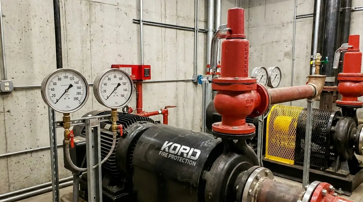
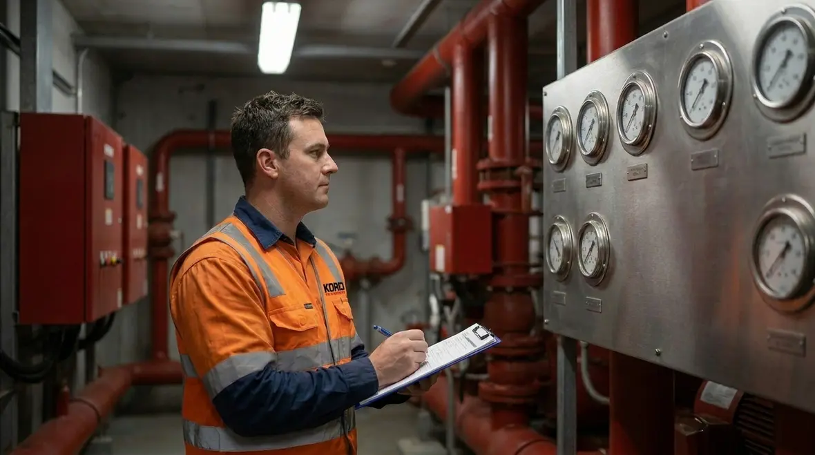
Gauges provide more than numbers on a dial. They give teams a snapshot of pump performance at the moments that count. When NFPA 20 requirements call for gauges, the goal stays consistent: staff must be able to observe pressure at relevant points so they can confirm the pump curve and system behavior during testing.
For many facilities, the real challenge is not reading the gauge during a test. The real challenge is recognizing what changes mean when the system runs for months. Over time, sensors can drift, fittings can corrode, and gauge locations can become less useful if piping modifications occur. Therefore, teams should treat gauge accuracy and placement as part of the protection strategy.
In practice, facilities can benefit from these discipline points:
- Correct gauge type and range so the display stays meaningful during both normal operation and abnormal conditions.
- Proper installation and isolation so water hammer and vibration do not damage the gauge or distort readings.
- Clear labeling so technicians can interpret results quickly without guessing which line they are looking at.
- Routine verification during service visits to catch drift early, before it hides a real issue.
Meanwhile, this monitoring layer supports other parts of the system. If a relief valve starts operating differently, or if equipment protection devices indicate stress, gauge trends often provide the first clue. That is when the pump stops being a black box and starts behaving like a measurable system.
Relief valves: controlling pressure and protecting the pump
Why the valve matters when conditions shift
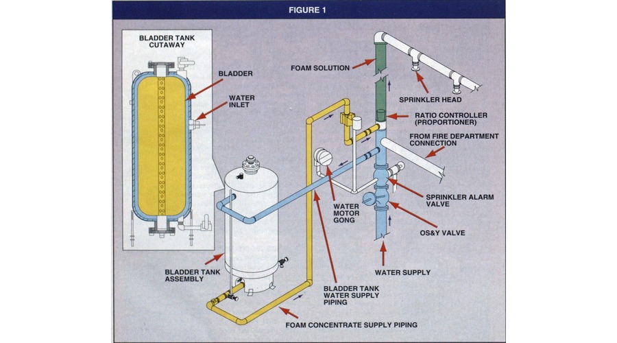
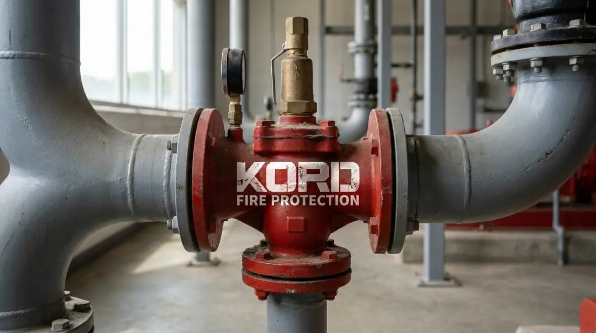
Relief valves exist for a reason. When flow patterns change or demand varies, pumps can face conditions that create excessive pressure. The relief valve gives excess energy a safe path, reducing the risk of damage and helping the pump maintain a controlled operating state.
However, a relief valve is not a “set it and forget it” component. It must match system design, remain unobstructed, and function as intended when testing shows it should. Over time, valves can stick due to debris, scale, or poor water quality. Additionally, a valve that is physically installed correctly but poorly maintained can still act incorrectly.
Kord Fire Protection can support teams by integrating relief valve checks with gauge observations and equipment protection review. This approach reduces the chance of diagnosing one symptom while missing the root cause. After all, the relief valve does not live alone; it operates within the pump assembly and the piping network.
Facilities also benefit when relief valve work includes:
- Verification of discharge arrangement so water does not create hazards or interfere with safe operation.
- Inspection for leaks and interference that can develop around seats and connections.
- Testing during service to confirm correct response under real conditions.
When this work aligns with the rest of the pump plan, it reinforces fire pump gauges relief valves equipment protection as a whole system, not as separate checklist items.
Equipment protection: preventing damage from poor conditions
Protection devices also tell a story
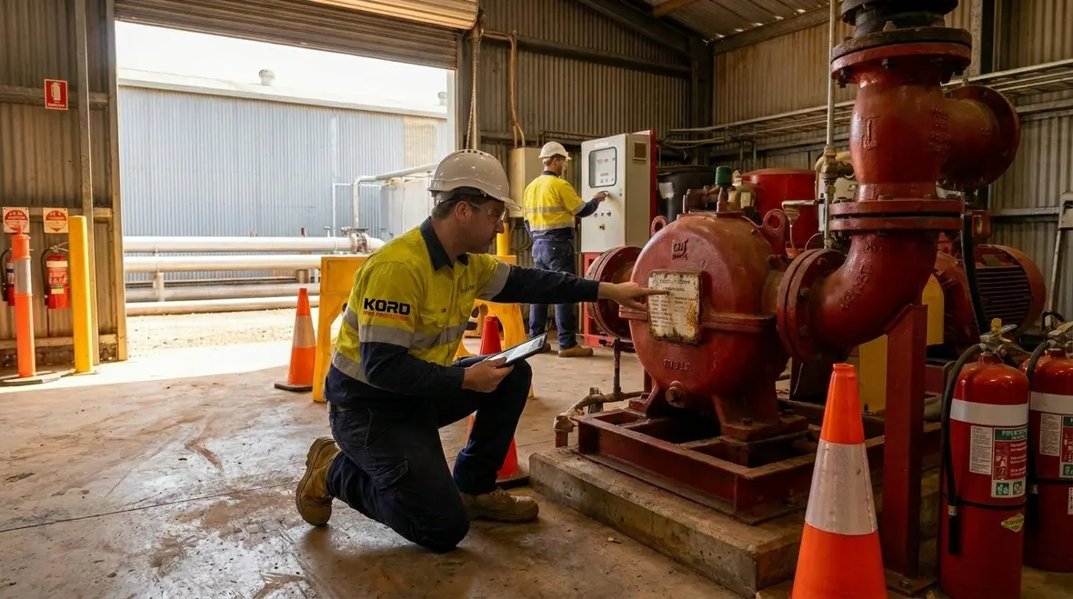
Equipment protection measures help stop harmful conditions from turning into costly repairs. In pump systems, protection focuses on keeping the pump and related components within safe operational limits. When protection triggers, it often signals that the system is experiencing flow, pressure, or water supply conditions that could threaten performance.
Therefore, protection is not just a “safety feature.” It is also a diagnostic tool. If a protection device activates, the facility team should treat it as data, not as a nuisance event. The goal stays simple: keep the pump healthy and the system ready.
In industrial, retail, and commercial facilities, common contributors include supply fluctuations, changes to connected pipework, and water quality issues. Even a small modification to a service line can affect performance behavior. As a result, equipment protection checks should work alongside a review of how the pump system connects to the broader site.
What Kord Fire Protection adds as a partner is the practical link between requirements and maintenance outcomes. Kord can coordinate service activities, ensure the right tools and procedures, and document findings in a way that helps facilities make decisions quickly. In busy operations, that calm, structured approach matters.
How to build compliance into ongoing service
Turn one-off checks into a usable workflow
Compliance only lasts if it survives real life. NFPA 20 requirements become meaningful when teams schedule service actions that keep gauges accurate, relief valves responsive, and equipment protection intact. However, many sites struggle with fragmented responsibilities across maintenance contractors, fire system technicians, and facility engineers.
To reduce that friction, facilities can use a service structure that connects the system components. Then, they can track issues as patterns rather than one-off problems.
A practical service workflow often includes:
- Pre service review to identify recent alarms, past test results, and any recent site changes.
- Gauge and reading checks to confirm pressures are stable and match expected behavior.
- Relief valve inspection and functional confirmation so valves open and control excess pressure correctly.
- Equipment protection verification to ensure safeguards activate and reset as designed.
- Clean documentation so the next service visit starts with clarity, not guesswork.
And yes, paperwork matters. But paperwork without system understanding is like owning a smoke alarm and ignoring it when the battery starts chirping. It still “works,” technically. It just wastes time and trust.
By integrating fire pump gauges relief valves equipment protection work into the same service visit, Kord Fire Protection can help facilities maintain a consistent picture of pump health across multiple locations.
Common issues seen during audits and inspections
Why a component can look fine and still perform badly
Even when facilities follow schedules, audits often reveal issues that only show up when someone checks closely. For example, gauges can appear present but fail to show reliable readings. Relief valves can look intact while their response changes after years of operation. Equipment protection can be functional but not aligned with updated piping behavior.
Typical findings include:
- Gauge inaccuracy or poor readability due to drift, damage, or unclear labeling.
- Sticking relief valves caused by debris or scale that alters response.
- Unexpected pressure conditions that suggest flow restrictions, valve mispositioning, or water supply variation.
- Protection devices affected by access or maintenance gaps so they cannot perform as designed when stress occurs.
When Kord Fire Protection supports this work, it helps facilities move beyond “pass or fail” results. Instead, teams can identify why performance shifts and how to keep the pump system stable across seasons and operating modes.
FAQ: NFPA 20 gauges, relief valves, and equipment protection
Conclusion: choose support that keeps the system dependable
NFPA 20 Sections 4.10 to 4.12 ensure fire pumps stay measurable, controlled, and protected through fire pump gauges relief valves equipment protection. Facilities that treat gauges, relief valves, and safeguards as one connected system reduce downtime and improve confidence during inspections.
Kord Fire Protection can become the partner that manages the job with clarity and consistency. Reach out to plan your next service visit and keep the pump ready, no drama required.

Join Our Newsletter!
Get the latest fire safety tips delivered straight to your inbox From our Newsletter.