NFPA 20 4.18 to 4.22 Relief Valves, Flow Testing and Flow Meters
Quick Answer: NFPA 20 Sections 4.18 through 4.22 set practical rules for relief valves, flow testing, hose manifolds, and flow meters. These items help a pump system perform as designed and stay compliant across demanding Australian industrial and commercial sites. Kord Fire Protection supports inspections, upgrades, and documentation so teams can move with confidence.
In Australia, fire pump performance cannot be a “hope and a prayer” situation. Within the first setup and ongoing service, the fire pump flow meter and relief valve requirements help prove that water moves where it must, at the right pressure, under real conditions. NFPA 20 Sections 4.18 to 4.22 focus on the equipment and the checks that make the system trustworthy. And while that may sound like paperwork dressed as engineering, it actually protects lives and limits downtime when the stakes get real.
For facilities planning service work early, Kord Fire Protection’s full fire protection services can sit naturally alongside fire pump compliance planning, especially where testing, documentation, and system readiness need to stay coordinated across one site. For the broader code context behind these sections, it also helps to review how NFPA 20 regulates fire pump systems. ([kordfire.com](https://kordfire.com/full-fire-protection-services/?utm_source=openai))
NFPA 20 4.18 and 4.19: Relief valves that behave like they mean it
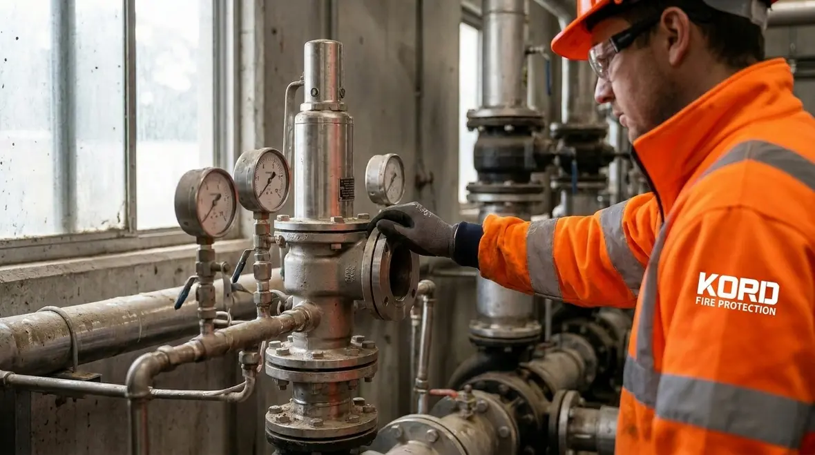
NFPA 20 Section 4.18 addresses relief valves for fire pump systems. In plain terms, a relief valve provides a controlled path when the pump needs to relieve pressure. That matters because operating conditions can change due to demand, test setups, or system layout.
Section 4.19 then supports flow testing expectations tied to system performance. Therefore, the relief valve must not only be installed, it must be set and verified in a way that supports the pump’s job. Otherwise, the pump can look fine on paper and still act unpredictably during real discharge.
When teams align the hardware to the relief valve requirements, they reduce the odds of nuisance alarms, unstable pressure readings, or prolonged abnormal operation. And let’s be honest, no one wants a fire pump to perform like a dramatic actor at the end of a season. Reliable components perform quietly.
Why relief valve setup affects the whole pump system
This is where practical service matters more than theory. A relief valve that is technically present but poorly adjusted can distort testing outcomes, mask pressure control issues, or create confusion during inspections. Teams may chase symptoms in the flow data when the real issue sits inside the pressure relief arrangement. That is not just annoying. It can also slow corrective action when the site needs clear answers fast.
Flow testing under NFPA 20 4.19: Proving performance, not guessing
Flow testing is where compliance becomes real. NFPA 20 Section 4.19 supports testing methods that check how the system delivers water. In practice, the test verifies pump curve behavior, pressure at flow, and system response to actual demand.
To do this well, service teams should plan for the test conditions, confirm instruments, and make sure readings represent the system, not the tester’s setup. Then they document results in a way that supports audits and future troubleshooting.
For facilities across Australia, this testing becomes even more important due to the variety of system designs found in industrial, retail, and commercial spaces. A warehouse facility with long pipe runs may behave differently than a retail property with shorter distribution. Therefore, testing must match the actual configuration.
One more practical point: flow testing protects operations. If a fire pump underperforms, the first sign might show up during a routine inspection, not during an emergency. That early warning can save time, money, and nerves, which is great because nerves cost more than anyone admits.
What good flow testing documentation actually does
A solid test does more than satisfy a checklist. It creates a baseline for future service, helps technicians compare changes over time, and gives site managers something better than memory when questions come up months later. If a pump starts drifting from expected performance, documented flow and pressure readings show whether the issue is sudden, gradual, or tied to a recent system change. That makes troubleshooting much less theatrical.
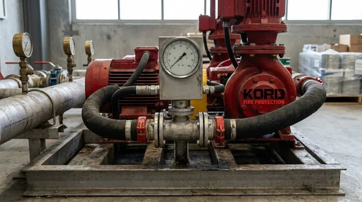
Flow meters and fire pump flow meter placement: measuring like a pro
NFPA 20 Section 4.20 covers hose manifolds, and Section 4.22 covers flow meters. The key idea is simple: if the system uses the wrong measurement approach, it can mislead everyone who relies on the numbers.
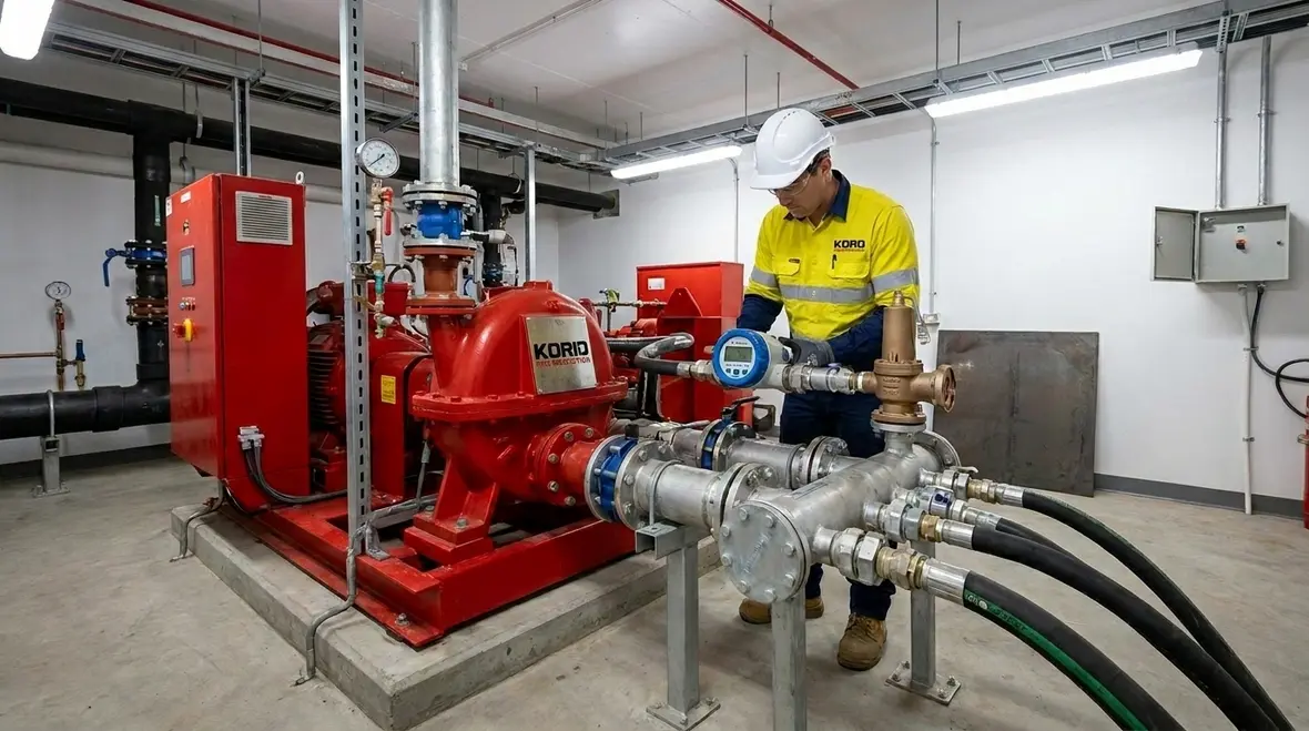
A fire pump flow meter provides evidence of water discharge during testing and operation. Thus, it needs to be installed with correct orientation, proper connections, and consistent setup. It also needs to be checked for calibration and accuracy over time.
However, measurement accuracy depends on more than the meter itself. Piping design, fittings, and straight-run requirements affect flow readings. In addition, changes like valve replacements or pipework modifications can shift system hydraulics and readings. So, the meter should not be treated as a set-and-forget device.
Service teams that address meter placement and test integration help ensure that flow readings align with discharge performance and documented results. That makes compliance smoother and repairs more targeted, which is the dream scenario for any site manager.
Why placement errors create expensive confusion
When a flow meter sits in the wrong part of the piping arrangement, the numbers can look official while telling the wrong story. That can lead teams to blame the pump, the controller, or the water supply when the real problem is measurement setup. Good placement reduces false conclusions, shortens service time, and gives everyone cleaner evidence to work from. In a field full of moving parts, honest data is a gift.
Hose manifold details under NFPA 20 4.20: Ready access for dependable use
NFPA 20 Section 4.20 addresses hose manifolds as part of the fire pump system arrangements. Hose manifolds connect hoses for use by trained personnel. Therefore, they must support quick access, proper connection, and safe operation.
Technically, the manifold arrangement connects into the system piping so that hoses can draw water at the expected pressure. If the manifold layout, valves, or connections fail to match the system design, then hose use can become ineffective or inconsistent.
And because industrial and retail sites use different water demand strategies, manifold configurations vary. That means a one-size-fits-all approach does not work. Instead, competent service teams consider the site’s operational needs, the water supply design, and maintenance access.
When a team verifies the manifold arrangement during service, it reduces surprises and supports future testing. It also helps keep staff prepared, which matters because in an emergency, speed is not a slogan, it is a requirement.
Where manifold checks fit into real maintenance planning
Manifold details are easy to ignore until they become inconvenient. Yet access, valve condition, connection type, and surrounding clearance all affect whether the arrangement is practical during testing or emergency use. A site that reviews these details ahead of time avoids awkward surprises later, which is a polite way of saying fewer frantic phone calls and less blame flying around the pump room.
Testing with relief and flow instruments: keeping the loop closed
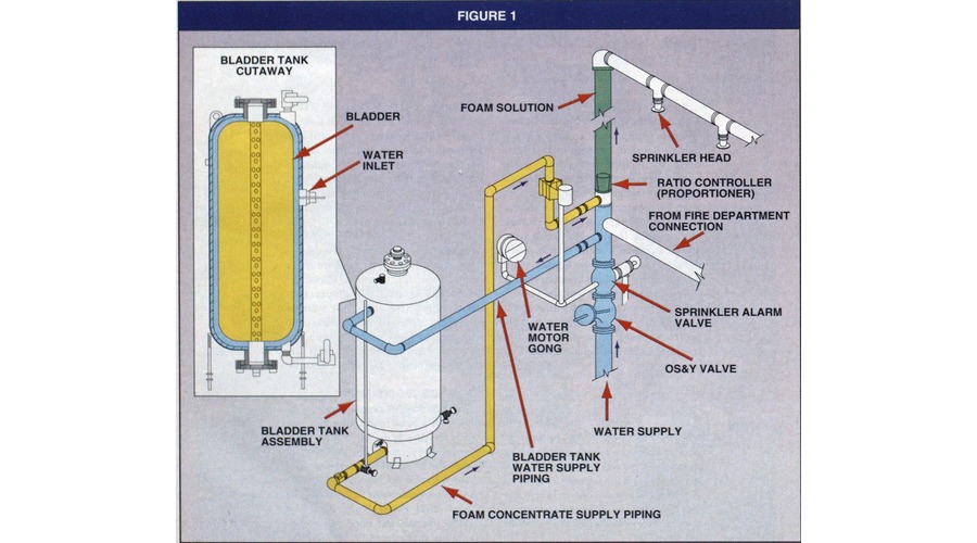
Sections 4.18 through 4.22 connect into one idea: the system must relieve correctly, move water predictably, and report performance accurately. So, service teams should treat relief valves, hose manifolds, and flow meters as one coordinated system.
During testing, they should compare relief response with measured flow and pressure. If the pump’s measured delivery does not match expectations, they should then check the flow meter readings, valve positions, and system configuration. After that, they can verify relief valve behavior and settings.
In other words, they should close the loop between what the equipment does and what the measurements claim. That is how facilities avoid “mystery failures,” where everyone argues about what happened until the next test finds the same problem wearing a new hat.
For Australian facilities, this structured approach supports both compliance and operational continuity. It helps avoid prolonged downtime during service visits, and it supports clearer work orders when upgrades become necessary.
A smarter way to interpret conflicting readings
If pressure, flow, and relief behavior seem out of sync, the answer is rarely to guess louder. A coordinated review helps teams identify whether the issue comes from instrumentation, hydraulic changes, valve settings, or actual pump performance. That method keeps maintenance grounded in evidence. It also helps managers approve repairs with more confidence, because the recommendation comes from a tested chain of logic instead of a shrug in steel-toe boots.
Kord Fire Protection as a vital partner for compliant performance
Kord Fire Protection supports fire pump service across industrial, retail, and commercial sites in Australia. Therefore, when a facility needs work aligned with NFPA 20 Sections 4.18 through 4.22, Kord can act as a vital partner that handles the technical details and the documentation trail. Kord’s own related resources on fire pump controller reliability, routine fire pump maintenance, and broader Australia fire protection readiness reinforce the same connected approach to testing, service, and compliance planning. ([kordfire.com](https://kordfire.com/electric-fire-pump-controller-reliability-in-australia/?utm_source=openai))
They help facilities plan service around flow testing needs, verify relief systems against the relief valve requirements, and make sure the fire pump flow meter setup supports accurate readings. Then they assist with maintenance workflows that reduce disruptions. In the real world, that often matters more than anyone wants to admit during the first phone call.
Also, when sites need upgrades, Kord can support the conversation with practical guidance based on measured outcomes. That means decisions rely on evidence, not vibes. And for fire pump systems, evidence is the only kind of confidence worth having.
FAQ
Conclusion
When NFPA 20 Sections 4.18 through 4.22 receive careful attention, fire pump systems deliver predictable performance, and compliance becomes a process instead of a panic. Relief valves, hose manifolds, flow testing, and flow meters all contribute to one result: a system that can be trusted when conditions are anything but calm.
Kord Fire Protection helps facilities in Australia verify relief valve performance, support flow testing, and ensure flow measurement aligns with real system delivery. If your site needs confident results and clean documentation, contact Kord Fire Protection and get the work done right.

Join Our Newsletter!
Get the latest fire safety tips delivered straight to your inbox From our Newsletter.