NFPA 15 Section 8.1 Fire Spray System Plans and Hydraulic Calculations
Quick Answer: NFPA 15 Section 8.1 sets the foundation for fire spray system design by requiring clear general plans and solid hydraulic calculations. In simple terms, it helps ensure the system delivers the right water, at the right pressure, to the right place. For industrial, retail, and commercial sites across Australia, that means safer operations and fewer surprises.
NFPA 15 plans hydraulic calculations general work sits at the heart of reliable fire protection design. Under Section 8.1, the design team must show enough detail to prove the system will perform as intended during a fire event. That means clear plans, correct water supply data, pipe sizing, nozzle layout, and pressure checks that all line up. In the real world, this is not just paperwork. It is the difference between a system that looks good on a drawing and one that actually behaves when things get hot, which, to be fair, is when everyone prefers the equipment to do its job.
For businesses across Australia, from warehouses to shopping centres to heavy industrial sites, the value of this process is hard to miss. It supports compliance, helps reduce risk, and gives owners a more dependable fire protection strategy. Kord Fire Protection can play a vital role here, because a service like this demands practical field knowledge, careful engineering, and a firm grip on local project needs. In other words, the drawings must speak fluent real world, not just fluent acronym. Near the start of that process, it also helps to connect the documentation effort with broader fire sprinkler services so design intent stays practical in the field.
What NFPA 15 Section 8.1 Requires
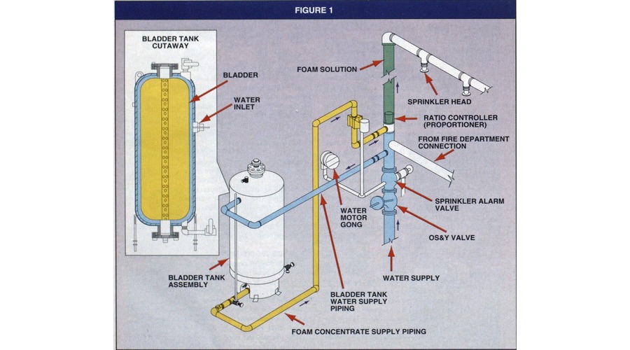
Section 8.1 focuses on general plans and hydraulic calculations for water spray and fixed fire protection systems. The goal is simple. The designer must prove the system can deliver the required water density and coverage across the protected hazard. Therefore, the plan must show the full layout, the hazard area, the supply source, valves, piping arrangement, nozzle placement, and the design basis used for the calculations.
Just as important, the hydraulic data must show that the system can meet the demand at the most remote and critical point. That includes pressure losses in pipe runs, fittings, elevation changes, and any device that affects flow. Without that proof, the design remains theory. And theory is nice in a classroom, but a fire system needs a little less philosophy and a lot more pressure.
The Core Documents the Design Team Must Get Right
This is where a lot of projects either gain momentum or quietly step on a rake. If the general plans are vague, everyone downstream pays for it. Reviewers ask more questions. Installers make assumptions. Owners end up wondering why a system that sounded straightforward now needs another round of revisions. A proper Section 8.1 package should remove that uncertainty by making the design intent obvious, defensible, and buildable from the start.
Why Detailed Plans Matter for Industrial and Commercial Sites
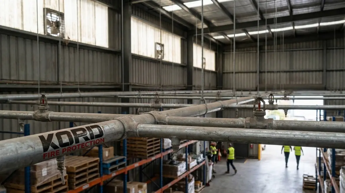
Industrial and commercial facilities usually have larger hazards, tighter deadlines, and more moving parts than people care to count. Because of that, the general plans must give builders, reviewers, and owners a clear picture of the system scope. The plans also help avoid clashes with mechanical services, electrical gear, storage racks, and operational access paths.
Moreover, detailed plans support faster approvals and smoother installation. When drawings are clear, installers spend less time guessing and more time building. That saves money, reduces site delays, and cuts down on the classic project drama where one trade says, “It was on the drawing,” and another says, “No, it was never on the drawing.”
That clarity matters even more in facilities that evolve over time. Warehouses expand. Retail tenants rework layouts. Industrial sites add equipment that suddenly occupies the exact space a pipe route once loved. Good plans create a reference point that helps teams adapt without losing the original hydraulic intent. If that sounds boring, fair enough, but boring documentation is often the reason a project avoids exciting problems later.
How Hydraulic Calculations Protect Performance
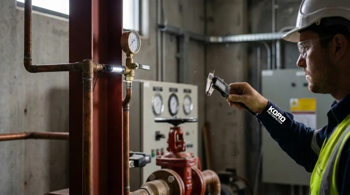
Hydraulic calculations answer the key question: will the system work under real demand? They confirm whether the available water supply can support the design flow and pressure. In practice, this means the engineer checks pipe friction loss, nozzle demand, elevation effects, and the capacity of the water source.
These calculations matter because fire protection systems do not forgive guesswork. If the pressure is too low, the spray pattern may fail to cover the hazard. If the flow is too weak, the system may not control the fire fast enough. Therefore, the calculation package becomes a safety tool, a compliance tool, and a design check all at once.
What the Numbers Are Actually Proving
The numbers are not there to impress anyone with decimal places. They show whether the design still performs at the most demanding point in the system, after friction, fittings, distance, and elevation have taken their share. That is why teams pay close attention to static and residual pressure, available flow, pipe sizes, and nozzle demand. It is also why coordination with related planning can help, especially when a project draws from broader design thinking such as sprinkler system hydraulic calculations basics that explain how the math and the drawings need to support each other.
Plan Details That Support Section 8.1
- General site layout
- Hazard boundaries
- Pipe routing
- Nozzle locations
- Water supply point
- Valve and control locations
Calculation Data Often Included
- Available water flow
- Static and residual pressure
- Pipe sizes and lengths
- Fitting losses
- Elevation changes
- Design density or discharge demand
Where Kord Fire Protection Adds Real Value
Kord Fire Protection can become a vital partner because this work needs more than a template. It needs experience across design, documentation, installation support, and project coordination. As a result, Kord can help clients turn NFPA 15 requirements into practical, buildable, and compliant fire protection solutions.
For Australian industrial, retail, and commercial facilities, that support is especially useful. Site conditions change. Water supplies vary. Existing services often crowd the ceiling space like they own the place. Kord Fire Protection can help manage these issues early, which reduces redesign, limits rework, and keeps the project moving. In addition, a capable partner can help align the system design with local expectations, site rules, and operational needs.
That practical advantage becomes easier to appreciate when a facility needs more than isolated drawings. It often needs a connected strategy that ties suppression planning to field realities, coordination, and long term readiness. Kord’s related guidance on NFPA 15 water spray fixed systems also fits naturally here, because it reinforces how design requirements translate into actual protection outcomes.
How Project Teams Can Avoid Common Mistakes
Even strong projects run into trouble when the plan lacks detail or the hydraulic data is weak. One common mistake is using incomplete water supply information. Another is ignoring pressure loss from long pipe runs or dense fittings. Sometimes teams also miss practical site issues, such as access limits, future storage changes, or equipment relocation.
To avoid those problems, the design team should confirm field data early, review the hazard layout carefully, and test the calculation assumptions before drawings move ahead. Furthermore, they should keep communication open between the designer, builder, and owner. That approach may not sound glamorous, but neither does a fire incident. And yet, one gets everyone’s full attention rather quickly.
Another smart move is treating constructability as part of safety, not a separate conversation that appears after everyone’s schedule is already on fire, metaphorically speaking. If pipe routing, valve access, and service clearances are considered early, the installed system is much more likely to match the documented system. That is a small miracle in construction terms, and a very useful one.
How NFPA 15 Support Helps Long Term Operations
A well prepared plan and calculation package does more than satisfy a review. It also helps with maintenance, future upgrades, and asset management. Facility teams can use the drawings to understand system zones, isolate valves, and plan inspections. Likewise, the calculation record creates a useful baseline if the site expands or changes storage patterns later on.
That long term value matters in busy Australian facilities where operations cannot stop every time a new tenant moves in or a process line changes. A clean, accurate design record helps keep fire protection aligned with the real site, not the site from three renovations ago that nobody wants to talk about anymore.
It also gives owners and facility managers something rare and beautiful: a document trail that makes sense. When inspection teams, service providers, and future designers can understand what was intended, they can make changes without unraveling performance. That turns Section 8.1 from a design requirement into a long term operational asset, which is not the flashiest compliment a document package can receive, but it is one of the best.
FAQ
Conclusion
NFPA 15 Section 8.1 demands careful plans, accurate hydraulic calculations, and practical thinking. For Australian facilities, that means better protection and less risk. Kord Fire Protection can help turn that technical work into a dependable project outcome. For teams that want a clear path from design to delivery, the next step is simple: bring in the right partner early and let the system be built to perform.
- Clear plans reduce confusion and rework
- Hydraulic calculations confirm real performance
- Better documentation supports approvals and maintenance
- Early coordination helps projects stay buildable
- Kord Fire Protection adds practical project value

Join Our Newsletter!
Get the latest fire safety tips delivered straight to your inbox From our Newsletter.