NFPA 15 Section 5.8 Pressure Gauges: Scale and Location Requirements
Quick Answer
NFPA 15 Section 5.8 requires pressure gauges that clearly indicate system pressures and can support reliable operation, commissioning, and inspection. This includes gauge scale selection tied to expected readings and a location that enables safe, accurate measurement during testing. Proper placement also supports ongoing maintenance and compliance evidence.
Facilities that want to keep those readings meaningful over time should also review fire protection inspection, testing, and maintenance services, since gauge readability is only useful if someone is actually checking it before the next headache arrives.
Why NFPA 15 5.8 pressure gauges matter in real sprinkler and water spray operations
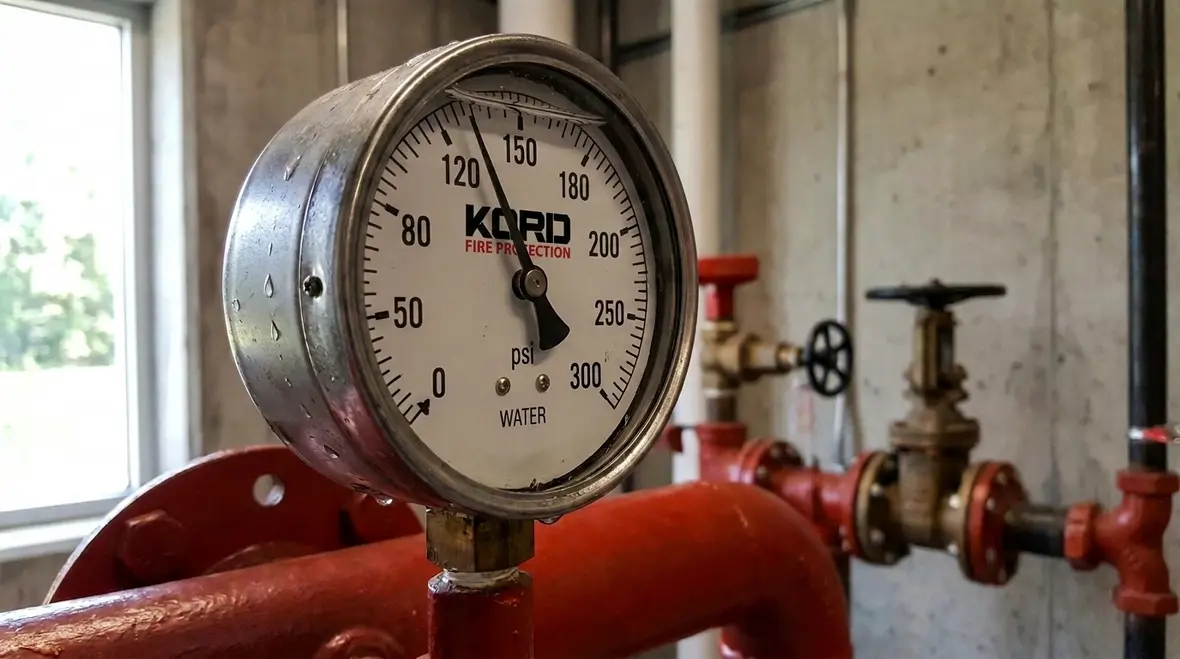
In commercial and industrial water based fire protection systems, pressure gauges act as the practical measurement tool that links design intent to operational performance. NFPA 15 5.8 pressure gauges listed twice working pressure drives two compliance outcomes: the gauge must have a usable scale and it must be installed where technicians can read it accurately without compromising safety or system function. When scale or location is wrong, field readings become misleading, acceptance testing becomes disputed, and maintenance records become difficult to defend.
Fire protection contractors and facility teams commonly encounter recurring friction points during acceptance, periodic inspection, and impairment investigations. These include gauges installed with scales that do not allow meaningful interpretation, shutoff valves and fittings that obstruct visibility, or placements that force technicians to access equipment in unsafe positions. The result is not only nonconformance risk but also increased downtime when remedial work becomes necessary.
For broader fixed water spray system context, see: NFPA 15 enhancing fire safety with water spray fixed systems.
What NFPA 15 5.8 requires about gauge scale
NFPA 15 Section 5.8 focuses on whether the gauge scale supports dependable readings at expected operating conditions. The key selection expectation is that the gauge is suitable for the system it monitors, and that the working pressure falls within the effective portion of the scale so readings remain precise during testing, normal operation, and troubleshooting.
Scale range selection tied to twice working pressure
A practical way facilities interpret this requirement is through the gauge scale statement commonly referenced as NFPA 15 5.8 pressure gauges listed twice working pressure. In practice, the scale range should be selected so that the expected working pressure is well represented and the gauge does not operate near the extreme end of its range where resolution and accuracy degrade. This improves the quality of commissioning data and reduces the chance that later inspections uncover “out of range” interpretation issues.
From an operational standpoint, gauge scale selection must support the following activities:
- Normal system pressure verification during routine inspection.
- Acceptance testing and system adjustment after installation or major repair.
- Impairment investigation and troubleshooting when discharge performance does not match expected hydraulics.
- Evidence documentation for insurers, AHJs, and internal life safety audits.
Accuracy limits and why “usable reading” matters
Even when a gauge’s maximum range is technically larger than the system pressure, the gauge may still fail the intent of Section 5.8 if the working pressure falls too close to the lower end, where dial resolution is less meaningful. Technicians need a readable portion of the scale to capture incremental changes, especially during flow testing and pump or controller commissioning. This is where “listed twice working pressure” selection becomes more than a phrase. It becomes a field usability requirement.
Where NFPA 15 5.8 pressure gauges should be located
Gauge location determines whether readings truly reflect system pressure at the intended measurement point. NFPA 15 5.8 pressure gauges listed twice working pressure is only one side of the compliance equation. The other side is physical placement, mounting method, and connection practice.
Location that supports safe access and accurate observation
Gauges should be mounted so that inspectors can view them directly during testing without reaching over hazardous hazards, rotating machinery, or standing in discharge paths. In commercial facilities, safe access also aligns with lockout and hot work procedures, because gauge replacement and valve access often require system shutdown and controlled depressurization.
Good gauge locations also minimize measurement distortion caused by local pressure loss or trapped air. A gauge installed too far from the actual monitoring point can show a lower or higher reading than expected, especially when system pressure fluctuates during pump startup, flow transitions, or water hammer events.
Avoiding common placement errors
Field teams commonly encounter these nonideal gauge arrangements:
- Gauges mounted where piping is noisy or vibratory, leading to needle bounce and inconsistent readings during inspections.
- Connections that create unnecessary restriction, such as undersized fittings or restrictive orifices that alter pressure at the gauge.
- Positions that trap air or sediment, which can skew readings in systems that have intermittent operation patterns.
- Inaccessible mounting, where ladder placement, confined spaces, or obstructions prevent proper reading verification.
These issues create a pattern: the facility later experiences recurring disputes about “what the gauge said” versus “what the system hydraulics predicted.” Installing the gauge at the correct location prevents those disputes and reduces corrective maintenance.
Operational testing: how gauge scale and location impact commissioning
Section 5.8 compliance becomes meaningful during acceptance and periodic testing. When scale and location support clear interpretation, technicians can document results confidently and quickly. When they do not, testing slows down and remedial work becomes more frequent.
During acceptance and flow verification
Commissioning typically includes verifying system pressure at the specified gauge point while confirming operational behavior such as pump start sequences, controller response, and flow demand conditions. A gauge installed in the correct location should reflect system pressure with minimal distortion from piping distance, fitting losses, or trapped air. A gauge with an appropriate scale selected around NFPA 15 5.8 pressure gauges listed twice working pressure supports precise reading, particularly during incremental adjustments.
During periodic inspections and impairment events
Commercial facilities often operate under tight maintenance windows and limited downtime tolerance. During periodic inspection, the facility expects a consistent gauge reading and a stable needle response. In impairment events, technicians rely on gauge evidence to assess whether pressure reduced due to a valve position issue, a control malfunction, a pump performance change, or hydraulic conditions affecting flow.
When gauge readings appear inconsistent, the root cause often traces back to one of these mechanisms:
- Dial scale mismatch that causes poor resolution at working pressure.
- Needle jitter from vibration or weak mounting.
- Pressure transmission problems from poor connection details.
- Gauge deterioration, including internal wear or inaccurate calibration drift.
Maintenance and verification: protecting compliance over the full lifecycle
Pressure gauges are mechanical instruments with service life limits. Compliance requires more than initial installation. It requires ongoing inspection, verification practices, and documented maintenance.
Inspection checks that technicians should standardize
A defensible maintenance routine should include:
- Visual verification of gauge condition, including glass clarity and proper needle movement.
- Check for leaks at the connection and fitting interfaces.
- Confirm gauge readability from the normal inspection position.
- Verify the gauge needle does not stick or lag during pressure changes.
- Confirm the installed gauge still matches the system design intent for scale and range.
Calibration and replacement triggers
Facility teams should define triggers for calibration or replacement based on observed behavior. Common triggers include repeated inconsistent readings during tests, physical damage, abnormal needle response, and evidence of drift compared with expected pressure trends during pump operation.
Kord Fire Protection supports commercial facilities by aligning gauge selection, installation verification, and ongoing maintenance documentation with NFPA 15 expectations. This includes helping teams avoid “installed once and forgotten” failures, where gauge drift or placement issues go undetected until a critical inspection window.
For additional industry reference on fire pump and system performance documentation, consult firepumps.org.
How Kord Fire Protection helps facilities stay inspection ready
Commercial life safety compliance succeeds when design intent survives the field, the commissioning process, and the maintenance cycle. NFPA 15 5.8 pressure gauges listed twice working pressure is a requirement that is easy to misapply during fast installation schedules, gauge swaps, or retrofit projects. Kord Fire Protection helps facilities reduce those risks through practical verification and maintenance planning.
- Pre installation verification: confirm gauge scale selection matches expected working pressure and can produce usable readings.
- Location and access review: ensure gauges are mounted for safe inspection and minimal pressure distortion.
- Commissioning support: document readings during acceptance and adjustment so future audits remain straightforward.
- Ongoing maintenance: implement routine checks, replacement planning, and service records aligned to inspection expectations.
Frequently Asked Questions
Call to action
Ensure every pressure gauge on your NFPA 15 water based fixed system supports accurate readings throughout commissioning and ongoing inspections. Engage Kord Fire Protection to verify gauge scale selection, confirm proper location, and implement maintenance practices that protect compliance evidence. Contact Kord Fire Protection today to schedule a compliance review and update your inspection readiness for the next testing cycle.

Join Our Newsletter!
Get the latest fire safety tips delivered straight to your inbox From our Newsletter.