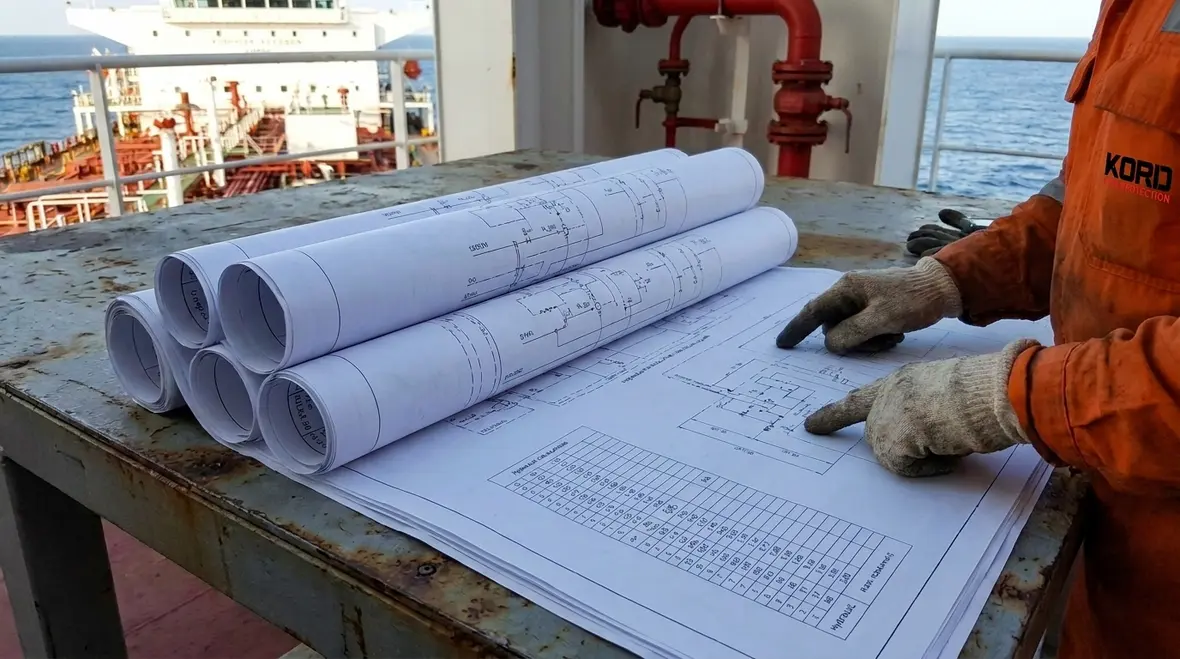
NFPA 13 Section 31.6 Marine System Plans and Calculations
Quick Answer: NFPA 13 Section 31.6 sets the plan and calculation expectations for marine fire sprinkler systems, including documentation quality, design basis transparency, and coordination needs unique to vessel environments. Proper NFPA 13 marine system plans calculations reduce approval friction and support inspection, testing, and maintenance.
Why Section 31.6 matters in marine sprinkler design
Marine systems do not behave like land based sprinkler installations. Motion, vibration, corrosion exposure, salt air, limited access for maintenance, and operational constraints for firefighting activities all influence hydraulic performance, reliability, and maintainability. NFPA 13 Section 31.6 addresses these differences by requiring plans and calculations that demonstrate the system will operate as intended within the marine context.
Design teams often underestimate how much detail marine authorities require in the drawing set and the calculation narrative. When documentation lacks clarity, approval timelines increase and the installation risks misinterpretation. This is why NFPA 13 marine system plans calculations must show a defensible design basis, not just “final numbers.”
For broader practical installation and lifecycle support, teams can also review fire sprinkler system service offerings from Kord Fire Protection near the start of planning, especially where documentation quality, inspections, and ongoing maintenance all need to stay aligned.
For a broader installation framework, teams can reference practical installation considerations in Kord Fire Protection’s NFPA 13 overview for automatic sprinkler systems.
What Section 31.6 requires in marine system plans
NFPA 13 Section 31.6 focuses on the completeness and traceability of the marine system submittal. Plans typically must provide enough information for verification, commissioning, and future maintenance. In practice, that means the drawings should allow reviewers to answer three questions quickly: What is being protected? How does water get to the hazard? And how does the system remain dependable in a marine environment?
1) System description that aligns with marine operations
- Identify the protected spaces and the hazard classification basis used for design.
- Describe the system type and intended performance for the marine setting, including how the design accounts for operating constraints.
- Clarify water supply arrangements and any dependency on pumps, tanks, pressurization sources, or fire main configurations.
2) Detailed layout that supports verification and field maintenance
- Provide piping layouts with correct routing logic for vessel compartments and access realities.
- Show sprinkler locations clearly, including orientation and coverage where applicable.
- Include identification for valves, waterflow devices, drains, and any sections that require special marine access considerations.
3) Component selections that remain maintainable afloat
Marine approval packages frequently scrutinize materials and components for corrosion resistance and serviceability. Plans should support this by clearly indicating the selected hardware and the reasoning behind those selections within NFPA 13 requirements and marine conditions.
Commercial operators also expect the submittal set to support routine inspection and service. If the plan set does not clearly indicate where isolation valves, test connections, and drains are located, testing becomes a disruption event instead of a controlled maintenance activity.
How NFPA 13 marine system plans calculations protect hydraulic performance
Calculations demonstrate that the system will provide required pressure and flow at the most remote and demanding points under design conditions. In marine NFPA 13 marine system plans calculations, the key difference is that the design basis must reflect the marine system constraints and operational intent, rather than assuming land based behavior.
Hydraulic design logic reviewers expect
- Demand analysis: Identify the design area or calculation method used and tie it to the hazard classification and sprinkler type assumptions.
- Supply and friction losses: Calculate friction losses through piping, fittings, and hose connections or test connections if included in the design pathway.
- Elevation and pressure relationships: Account for vertical height differences, water column effects, and any system elevation details relevant to the vessel layout.
- Safety margins: Demonstrate consistent assumptions that align with the system’s intended operating range.
Common calculation failure points in marine submittals
- Missing or inconsistent design assumptions: Using hazard classifications or sprinkler spacing assumptions that do not match the drawings.
- Incorrect “most remote” identification: Selecting the wrong remote point because the design does not fully reflect routing, valve positions, or compartment constraints.
- Friction loss mismatches: Using inconsistent pipe sizes, material roughness assumptions, or fitting loss logic across the plan set.
- Unclear water supply boundaries: Leaving pump intake conditions, pressure sources, and operating states under-specified.
When these issues appear, it often triggers rework across both calculations and drawings. That rework can be costly for industrial and retail facilities that share similar review expectations. Marine projects face the added cost of delayed fabrication and integration, which increases the benefit of high quality early documentation.
Coordination challenges: plans, pumps, and acceptance testing
Marine systems require coordinated design across piping, pumps, controllers, and water supply components. Section 31.6 plan documentation supports that coordination by enabling reviewers and installers to confirm the complete system performance concept.
Hydraulically reliable pump and water supply presentation
Pump performance, net pressure at the system, and operation under design conditions must align with the calculation results. In practice, teams should ensure the plans show how the pump curves, duty points, and operating modes support the required sprinkler demand.
For commercial teams that want a pump and firewater performance perspective, the operational concepts published by this NFPA 20 fire pump acceptance testing guide can support internal design review discussions and acceptance planning.
Field acceptance testing depends on plan clarity
Even the best calculations fail operationally if the system cannot be tested safely and repeatedly. Inspection and testing are easier when the drawings clearly indicate test locations, isolation strategies, and drainage pathways. This matters for commercial, industrial, and retail facilities because maintenance programs rely on predictable access and verification steps.
Inspection, maintenance, and long term compliance support
Section 31.6 documentation quality has direct downstream effects on inspection, testing, and maintenance performance. Marine operators often face restricted access, limited time windows, and higher corrosion risk. The plan set must therefore support a robust maintenance cycle, including the ability to isolate, test, and verify system operation.
Operational readiness and maintenance visibility
- Valves and test connections: Clearly identified to reduce time on board during maintenance.
- Drain and discharge management: Shown so testing does not create uncontrolled bilge or compartment impacts.
- Component access pathways: Indicated where space constraints affect reassembly and inspection.
Why ongoing service partnerships reduce compliance risk
Commercial stakeholders increasingly expect continuous compliance support, not just one time handover. Kord Fire Protection positions itself as a practical partner for ongoing testing, inspection readiness, and maintenance planning, which helps operators avoid drift between “as designed” and “as built.” For organizations that need a service lifecycle approach, Kord Fire Protection also supports installation and compliance alignment across project stages through its broader resources, including the NFPA 13 overview content.
International teams may also reference related capability information through kordfire.com.au and operational perspectives provided via kordelectric.com, where appropriate for coordinating multidisciplinary marine and commercial work scopes.
Frequently Asked Questions
Conclusion and next step
NFPA 13 Section 31.6 requires marine sprinkler plan sets and supporting calculations that demonstrate traceable, defensible performance and maintainability in vessel conditions. To reduce approval delays and avoid downstream rework, project teams should validate their NFPA 13 marine system plans calculations against the drawings, pump operating intent, and testing access needs. Contact Kord Fire Protection for a compliance focused document review, commissioning support, and ongoing inspection and maintenance planning to keep the system audit ready throughout its lifecycle.

Join Our Newsletter!
Get the latest fire safety tips delivered straight to your inbox From our Newsletter.