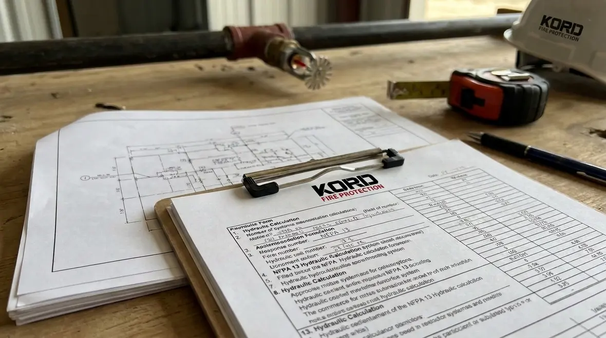
NFPA 13 Section 28.4 — Hydraulic Calculation Forms and Reports Guide
Quick Answer: NFPA 13 Section 28.4 guides how contractors document hydraulic calculations and submit sprinkler system reports. The goal is traceable, verifiable design data that supports field installation, inspection readiness, and ongoing maintenance. Proper forms reduce rework, speed approvals, and strengthen compliance.
Teams working through sprinkler documentation issues can also benefit from Kord Fire Protection’s sprinkler system hydraulic calculations basics for architects, which fits naturally here because it helps connect the math, the drawings, and the field reality before the awkward emails start.
Why Section 28.4 Matters for Commercial Sprinkler Compliance
In commercial facilities, the sprinkler system is not just installed. It must be documented. NFPA 13 Section 28.4 establishes the framework for hydraulic calculation forms and reports sprinkler design information so it can be reviewed, audited, and maintained over the life of the building. This is especially important where building approvals, insurance requirements, and ongoing inspections depend on consistent documentation.
Because authorities having jurisdiction and facility stakeholders often treat hydraulic documentation as a quality and safety record, weak or incomplete calculation submittals create practical risk: delays, costly field changes, and repeated verification. The keyword NFPA 13 hydraulic calculation forms reports sprinkler reflects the core need: standardized forms and clear reporting that tie design intent to the installed system.
What Section 28.4 Requires: Forms, Reports, and Traceability
NFPA 13 Section 28.4 focuses on documenting the hydraulic calculations in a way that supports accountability. While exact form content depends on the project approach and the design basis, the compliance expectation remains consistent: the report must allow another qualified party to understand how the system was designed, how flows and pressures were calculated, and what assumptions were used.
Key documentation elements typically expected in compliant submittals
- Design basis and system type: water supply characteristics, hazard classification basis, design area methodology, and system configuration.
- Calculation inputs and assumptions: pipe material data, roughness coefficients, elevation changes, and demand assumptions.
- Hose stream allowance and attenuation factors where applicable: values used and the reason they apply to the design.
- Flow and pressure results: required system demand points, remote area analysis results, and residual pressure comparisons.
- Hydraulic design node trace: how the remote area selection was determined and what area was ultimately used for the design.
- Sprinkler selection and performance data: including listing related parameters, temperature rating basis, and any specialty approvals that affect hydraulics.
Operational benefit: documentation that matches the installed system
Section 28.4 documentation becomes most valuable after installation when contractors and inspectors verify system performance. If the report aligns with the piping layout, sprinkler selections, and control valves applied in the field, then functional testing and maintenance planning becomes more efficient. If it does not align, the organization often faces hydraulic redrawing, partial retesting, and extended outage windows for corrective work.
How to Build Hydraulic Calculation Forms That Hold Up in the Field
Commercial projects often fail at the handoff stage, meaning the design paperwork does not match the as built constraints. A robust workflow reduces those gaps. Kord Fire Protection supports facilities by improving the quality of the documentation chain from design intent through installation verification and service readiness.
Step by step workflow for defensible hydraulics
- Confirm system information before calculations start: piping layout concept, building elevations, and required occupancy hazard inputs.
- Validate water supply data: review available flow test results, pump curve information, and any water storage strategy that affects pressure availability.
- Select the appropriate design methodology: verify remote area selection logic and ensure the model reflects the system layout.
- Run hydraulic calculations with controlled inputs: lock in sprinkler spacing assumptions, pipe lengths, fittings, and expected flow rates.
- Document results in report form: show required demands, available pressures at key locations, and the final design basis statement.
- Apply design results to field-ready outputs: ensure the selected remote area, density, and size selections reflect what installers can actually build.
- Close the loop at submittal: review with the contractor team so the as built scope matches the calculation assumptions.
Common Compliance Challenges in NFPA 13 Hydraulic Reporting
Many sprinkler disputes do not originate from the design calculations themselves. They originate from mismatches between design assumptions and field reality. Section 28.4 documentation should clearly identify what was analyzed so those mismatches can be evaluated quickly.
Top failure points that drive rework
- Water supply data mismatch: using outdated flow test results, ignoring seasonal variations, or applying incorrect pump curve data.
- Remote area selection errors: selecting the wrong area due to layout changes or incomplete review of ceiling obstructions and piping routes.
- Incorrect pipe and fittings accounting: missing fittings, incorrect fitting loss coefficients, or using inconsistent pipe schedule assumptions.
- Elevation and pressure adjustment mistakes: failing to accurately account for vertical lifts, drains, and system low points.
- Sprinkler substitution without hydraulic update: replacing a sprinkler type or orifice rating during coordination without rerunning calculations and updating reports.
- Field layout changes not reflected in the report: reroutes, ceiling modifications, and contractor value engineering that alters the hydraulic pathway.
Commercial facility reality: approvals and maintenance depend on records
Retail, industrial, and commercial office facilities often require ongoing compliance documentation for inspections and insurance underwriting. When the report package is complete, maintenance teams can plan replacement schedules, evaluate performance after renovations, and support inspections with confident historical context.
For a broader system installation context that aligns with how hydraulic documentation supports the project life cycle, review this overview: NFPA 13 overview for automatic fire sprinkler system installation.
Inspection, Testing, and Ongoing Maintenance Using the Section 28.4 Package
Hydraulic calculation forms and reports should not sit unused. Proper maintenance teams use the documentation to guide functional testing, evaluate changes, and reduce downtime during corrective work. Kord Fire Protection positions these records as part of the asset management process for sprinkler systems.
How the report supports field acceptance and service
- Hydrostatic and flow test planning: compare expected demand and pressure responses against installed configuration.
- Valve supervision and impairment tracking: connect documentation to operational controls so impairments do not compromise the system performance targets.
- After renovation review: verify whether tenant improvements alter sprinkler coverage, piping routing, or ceiling obstructions that affect hydraulics.
- Sprinkler replacements and upgrades: ensure replacements are consistent with the hydraulic assumptions in the NFPA 13 hydraulic calculation forms reports sprinkler package.
- Audit readiness for recurring inspections: maintain a clear record trail for AHJ or insurer requests.
Collaboration across the building team
Hydraulic documentation quality depends on coordination with electrical and facility systems for controls, pump operation, and emergency operations. Stakeholders often require a single source of truth. Kord Fire Protection helps keep the fire protection documentation aligned with the installed environment and the facility’s operational standards.
For related guidance on coordinated service and broader safety considerations, see: kordelectric.com and regional resources from kordfire.com.au.
External Reference Points for Design Verification and Industry Practice
Section 28.4 sits within the larger NFPA 13 design and documentation framework. When teams need additional industry context on water supply, pump planning, and system demand considerations, they can review: firepumps.org.
Using external references alongside the project’s own hydraulic calculations reduces assumptions, supports consistent terminology, and improves review speed during plan check and acceptance testing.
Frequently Asked Questions
Conclusion and Call to Action
Protect compliance outcomes by treating NFPA 13 hydraulic calculation forms reports sprinkler documentation as an operational asset, not a one time submittal. Kord Fire Protection can help verify documentation quality, support inspection readiness, and maintain alignment between the design package and the installed sprinkler system. Contact Kord Fire Protection to review your Section 28.4 documentation workflow and strengthen your facility’s long term sprinkler compliance posture.

Join Our Newsletter!
Get the latest fire safety tips delivered straight to your inbox From our Newsletter.