Industrial fire suppression electrical load calculations Australia
Quick answer: Calculating electrical load for fire suppression equipment means adding the power needs of each pump, controller, valve motor, fan, damper, and any alarm or interface devices. Then the designer checks voltage, starting current, voltage drop, and generator or UPS capacity. This prevents nuisance trips and keeps systems ready when it matters.
Early in planning, many sites also benefit from aligning these calculations with a broader fire pump electrical requirements and design review so the suppression strategy, controller behaviour, and power infrastructure are all speaking the same language instead of arguing across a switchboard.
Industrial fire suppression electrical load: where calculations start in Australia
In facilities across Australia, an industrial fire suppression electrical load is not a guess. It is a measured, documented design requirement that affects everything from main switchboard capacity to cable sizing, protection settings, and backup power. When teams get this wrong, the system does not just “underperform.” It can delay response, trip breakers, or fail during a worst case event. And yes, that is the kind of excitement most operators would like to avoid.
To stay accurate, contractors must treat the fire system as a set of electrical loads that behaves under real conditions: starting surges, control circuits, sequencing logic, and standby operation. Additionally, Kord Fire Protection can act as a vital partner during this service, helping teams align design intent with site conditions, device schedules, and documentation that survives audits and handover days.
What electrical load calculation includes for suppression systems
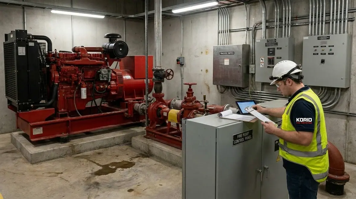
Fire suppression equipment rarely draws one tidy power number. Instead, it combines motor loads, control power, and communication interfaces. Therefore, the calculation must capture loads by function, not by wishful thinking. Typical contributors include:
- Fire pumps and their motor starters, including ramping or soft start equipment where used
- Jockey pump and booster pump loads, including running and start conditions
- Fire alarm panel power supplies and any supervised circuits
- Control relays, solenoid valves, and motor operated valves
- Fans, dampers, and actuators linked to smoke control or special suppression strategies
- Interface modules, panel communications, and watchdog power supplies
- Ancillary loads such as space heaters for pump rooms if they are required to meet duty cycles
Next, the design team gathers equipment nameplate data, manufacturer curves, and control sequence requirements. After that, the team confirms how the system is expected to operate during alarms and activation, because the electrical load in “standby” can look calm while the startup load is anything but.
Why the schedule of connected devices matters
A proper schedule does more than list equipment. It shows what starts first, what remains energized continuously, what only appears in alarm mode, and what shares a source with another life safety function. That matters because a panel, relay bank, or actuator that looks minor on its own can become very important when it joins a simultaneous event. A complete load schedule keeps the design grounded in reality instead of optimistic arithmetic.
Step by step method to size power, cable, and protection
To calculate the industrial fire suppression electrical load properly, teams follow a disciplined sequence. They do not just add kW and call it a day. First, they list each device and its electrical parameters. Then they compute total current for each operating mode.
The process often looks like this:
- Compile device data: motor kW, volts, full load amps, power factor, and starter type
- Identify operating modes: standby, alarm initiation, pump start, and simultaneous actuation
- Apply demand factors where permitted by project standards and design documents
- Calculate starting current effects, especially for direct on line starts or high inertia pumps
- Check voltage drop at the design current using conductor length and installation method
- Confirm cable ampacity and heat limits for both continuous and short duration loads
- Select protective devices: fuses, breakers, and overload protection with correct coordination
- Verify that backup systems can supply the required load for the specified duration
Consequently, the electrical design becomes a system-level check. It ties together power sources, protection, and device behavior. If the project includes a generator, the starting surges matter even more. Batteries handle controls, generators handle the heavy lifting, and together they decide whether the site can respond without drama.
Where cable sizing and protection coordination usually go sideways
The trouble often starts when teams size conductors for normal running current and forget the conditions that happen during startup, transfer, or a partial fault. Protection settings that look neat in a spreadsheet can become a problem if they trip before the pump settles, or if they fail to coordinate with upstream gear. The point is not simply to select a bigger breaker and hope for inner peace. The point is to build a chain of power delivery that remains stable through the ugliest moments of system operation.
That same discipline should continue into testing and maintenance. Kord’s article on fire pump testing requirements is a helpful related read because dependable electrical design and dependable pump testing are really part of the same story. One proves the system on paper. The other proves it in the real world where the paperwork has to earn its keep.
Starting current and sequencing: the part people underestimate
Here is the twist: motors can demand several times their running current for a brief moment. That starting surge can stress breakers, trip protection, and cause voltage dip that affects control electronics. Therefore, the design team must model the likely sequencing.
For example, during an alarm, multiple actions may occur in a tight time window. The system might start a jockey pump running, then ramp the booster pump, then open motor operated valves. Even if each component is “small,” together they can create peaks that surprise switchboard capacity calculations.
To handle this, the electrical designer must:
- Use the correct starter type assumptions, such as soft start, VFD, or DOL, for current profiles
- Model worst case simultaneous starts based on control logic
- Confirm that control power supervision does not drop during pump start events
- Check sensitivity of alarm panels and relays to voltage sag
And yes, if someone tries to “estimate it later,” that is like saying the fire will wait politely until the spreadsheet is finished. It usually does not work that way.
Dual power sources, UPS, and generator coordination
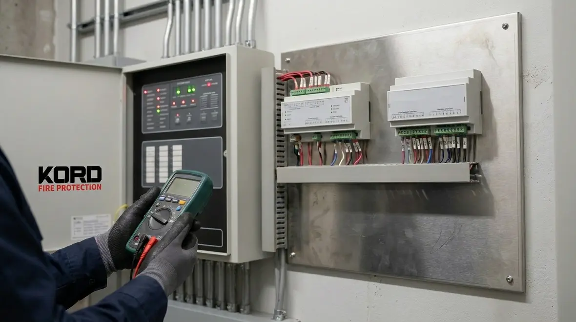
Across industrial and commercial facilities, designers must consider how the fire system stays powered during mains failure. Controls, panels, communication modules, and detection circuits often rely on dedicated supplies. Meanwhile, suppression pumps usually require generator or alternative power capability depending on the site design.
To coordinate this, engineers review:
- UPS sizing for control and alarm loads, including typical standby draw and battery runtime
- Generator start time, frequency regulation, and voltage stability during load pickup
- Transfer switch ratings and any permitted interruption time for control circuits
- Inrush and startup current handling limits for both generator and transfer equipment
Once these elements align, the site gains reliability. Yet the margin must still be correct. Overstating capacity can inflate costs; understating it can create a system that meets drawings but fails in real operation. This is where real coordination matters, and where a partner like Kord Fire Protection can help translate suppression design intent into electrical reality.
Backup power is only useful if the transition actually works
A generator with plenty of theoretical capacity does not solve much if transfer timing, voltage recovery, or control circuit behaviour are not checked under the same sequence the fire system will use. The practical question is simple: when utility power disappears, do the critical loads remain supported long enough and cleanly enough to keep the suppression strategy alive? If the answer is “probably,” the design needs more work.
How Kord Fire Protection supports electrical load planning
Calculating electrical load looks like an electrical task, and it is. However, fire systems live in the real world: equipment substitutions, site constraints, and commissioning findings can change the final load profile. Therefore, Kord Fire Protection can become a vital partner by supporting the full workflow, from device schedules to operational sequencing and handover documentation.
Typically, that partnership adds value by:
- Validating equipment selections and power requirements against the suppression strategy
- Supporting commissioning readiness, so the final system matches the design assumptions
- Helping teams align control logic with the electrical startup plan
- Providing practical guidance that reduces rework during installation and testing
- Improving audit and documentation outcomes through clear load and interface records
In other words, Kord helps ensure the calculated industrial fire suppression electrical load is not just “correct on paper,” but also correct in sequence, in commissioning, and in operation.
Featured FAQ: electrical load for fire suppression equipment
Conclusion: lock in correct electrical planning with Kord Fire Protection
Fire suppression electrical planning succeeds when teams calculate the load methodically, model starting peaks, and coordinate backup power. Then they install, test, and document the result so it performs during real events, not just inspections.
Kord Fire Protection can support this job as a steady partner across device alignment, sequencing, and commissioning outcomes. If a facility needs a clear electrical load basis for suppression equipment, reach out and get it right early.

Join Our Newsletter!
Get the latest fire safety tips delivered straight to your inbox From our Newsletter.