Fire Pump Motor Starter Issues Troubleshooting Guide
Fire pump systems do not fail politely. They fail when they are needed most, and that is exactly why fire pump motor starter issues deserve attention early. Common problems show up as motors that refuse to start, starters that trip again and again, and control boards that seem to “think” they are in a dramatic movie scene. And when that happens, kord fire protection technicians usually arrive calm, methodical, and ready to trace the fault step by step. Because starters involve power, protection, and control signals, small errors can snowball fast. Now let’s walk through the most frequent faults, how to spot them, and what the best field checks look like before anyone starts guessing.
Signs of trouble in fire pump motor starters
Before any tools come out, the technician should confirm what the system is doing. Then, they should match that behavior to a likely fault. Many sites see the same patterns, and they can point to issues in contactors, overloads, wiring, or sensing circuits. Kord fire protection technicians often begin with simple observations because it saves time and avoids unnecessary parts swaps.
- The pump does not start even though the demand signal exists
- The starter attempts to engage, then drops out quickly
- The motor starts, then trips on overload or ground fault shortly after
- Indicators show a lockout state, or the control panel reports an alarm
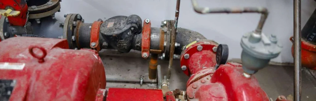
- Abnormal humming, buzzing, or heat near the starter enclosure
Once these clues show up, the team should move into checks that confirm power availability, control command, and starter logic. After all, jumping straight to blame feels like diagnosing a “flat tire” by staring at the wheel for ten minutes. It is not wrong, but it is not efficient.
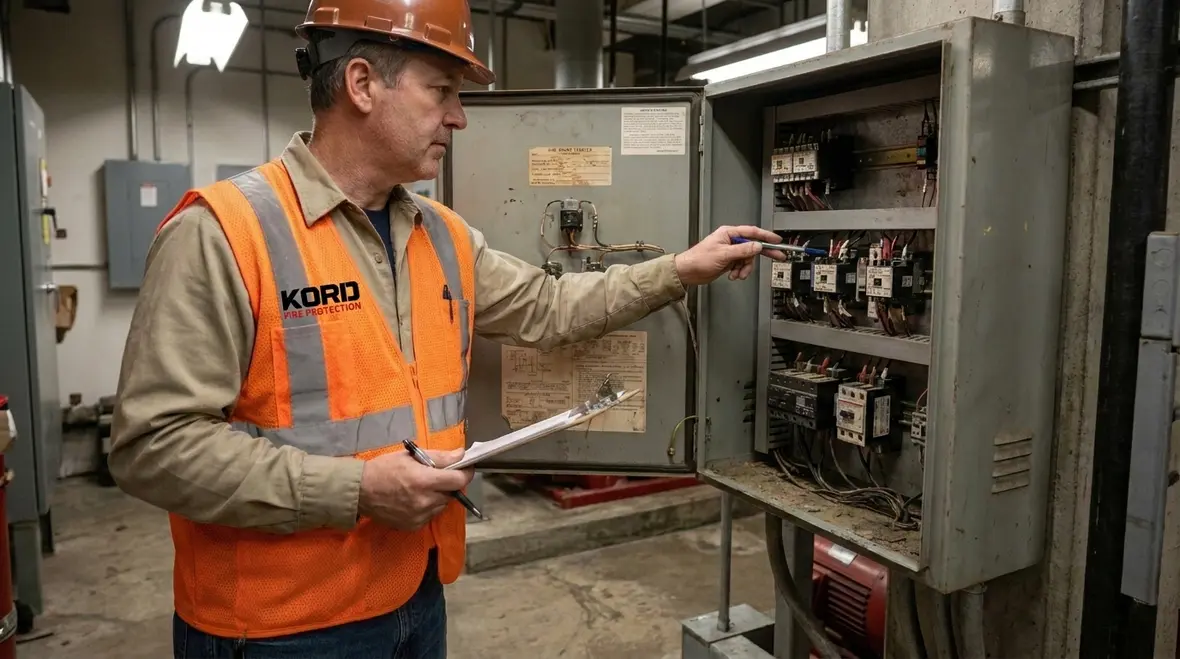
How technicians diagnose starter faults safely
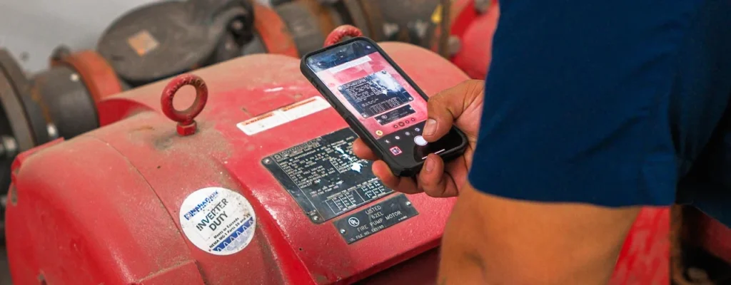
Safety comes first, and it stays first. Fire pump control circuits can carry hazardous voltage, and even small steps can create risk. Therefore, the technician should follow site lockout procedures, verify electrical absence where required, and confirm correct system mode. Next, they should record alarms, time stamps, and any recent changes like replacement parts or updated wiring. That way, the fault story does not disappear the moment the panel door closes.
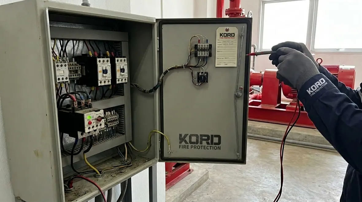
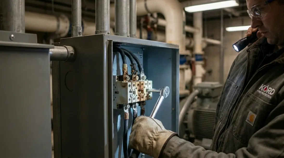
In the field, kord fire protection technicians typically use a structured path. They check incoming power, confirm control logic, inspect starter components, then verify motor feedback signals. Meanwhile, they also look for clues that suggest poor terminations, loose control conductors, or moisture problems inside the starter cabinet.
That sequence matters more than people think. If technicians skip the basic incoming power checks and sprint straight toward replacing parts, they risk solving the wrong problem very efficiently. A tripped protective device, a sagging control transformer, or a loose terminal can imitate a much bigger failure. Good troubleshooting is not glamorous, but it is fast in the long run because every reading has a purpose and every test narrows the field.
Safe diagnostic steps that save time later
- Confirm the fire pump controller is in the correct operating mode
- Review alarm history before resets erase useful clues
- Measure incoming line voltage and compare phases
- Verify control voltage at the exact point where the start path stops
- Inspect enclosure conditions for moisture, dust, heat, and corrosion
That last point gets overlooked constantly. The cabinet environment tells a story. Condensation, rust staining, insect debris, and darkened insulation are basically the starter’s way of waving both arms and asking for help. Ignoring those clues usually means the same issue comes back later with a bigger invoice attached.
Common control circuit faults that block start commands
When the motor refuses to run, the root cause often sits in control logic, not in the motor itself. So the technician should verify the command path: demand input, start permissives, control power, and interlocks. If any one link opens, the starter may stay silent, or it may show a lockout.
- Low control voltage prevents the contactor coil from pulling in
- Switches or relays fail to transfer, so the “start” command never reaches the coil
- Pressure switch or flow demand signals do not close correctly
- Interlock wiring opens due to damage, loose terminals, or corrosion
- Ground fault sensing circuits trip before the starter engages
Now, a frequent real world twist: the panel may indicate an alarm, but the alarm can get reset before the operator logs it. Hence, the best practice involves reading the event history while the information still exists. Because yes, the control cabinet can be like a celebrity at an award show: it leaves before anyone asks the right question.
Control circuit faults also create some of the most misleading symptoms. The contactor may chatter, the panel may flash an intermittent trouble, or the starter may respond once and then refuse on the very next demand. Those behaviors can point to unstable coil voltage, worn auxiliary contacts, or a weak relay that passes a bench check but fails under real conditions. That is why continuity alone is not enough. The circuit has to be checked under actual operating demand.
What technicians verify in the start command path
- Demand signal reaches the controller when pressure drops or a test command is issued
- All required permissives remain closed through the full sequence
- Control transformer output remains stable while the circuit is loaded
- Relay contacts transfer cleanly without delay or bounce
- Terminal screws are tight and conductors are not damaged at bends or edges
If the system has a documented maintenance history, this is also the time to compare current behavior to prior service notes. Repeated problems in the same section of the circuit usually mean there is an underlying condition still waiting in the wings, probably rehearsing for another dramatic entrance.
Overload, phase, and contactor problems during engagement
Even when the start command reaches the starter, problems can appear during engagement. At that stage, the technician should focus on phase conditions, overload settings, contactor health, and coil or linkage performance. If the starter pulls in and then trips, the sequence can reveal a lot.
- Incorrect phase wiring causes abnormal currents or immediate trip
- Overload relay trips due to high current, misadjustment, or component aging
- Welded or worn contactor contacts prevent proper drop out and create heat
- Loose motor leads cause voltage drop and increased current draw
- Thermal or mechanical issues limit contactor travel
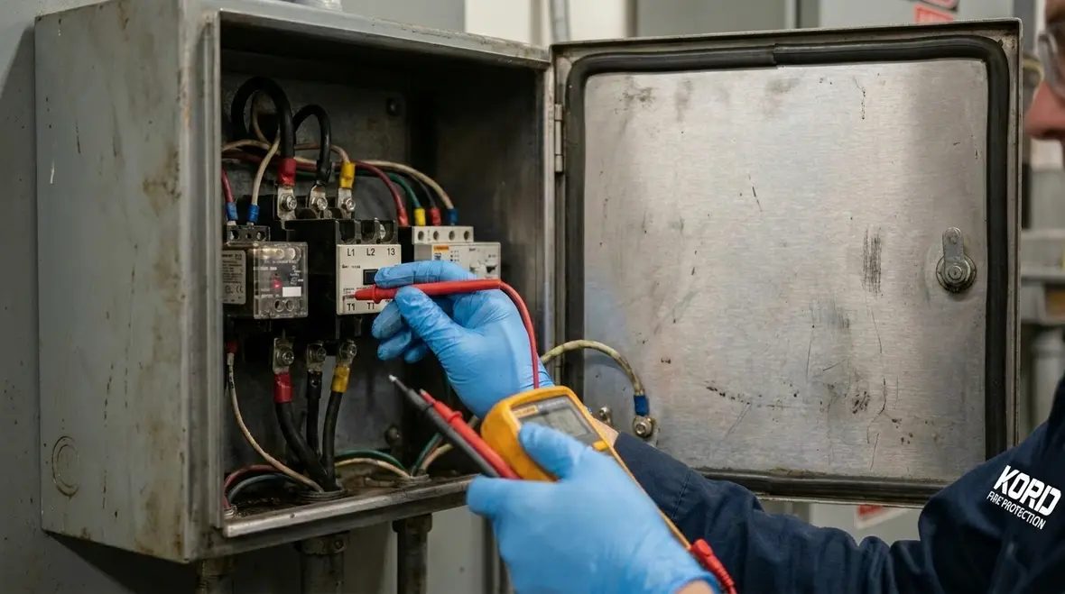
To move from suspicion to proof, the technician should measure current draw, confirm voltage at the starter input and output, and check that the overload relay resets correctly. Meanwhile, they should inspect contactor contacts for pitting or discoloration. Since fire pump performance depends on reliability, even “small” contactor defects can turn into expensive delays when the system is called to duty.
Phase related faults deserve extra respect because they can damage equipment quickly. Imbalance, loss of phase, or poor terminations on one leg can produce heat and uneven current that looks minor on the first inspection and ugly a little later. Likewise, overload devices need to be matched to the application and settings reviewed against the actual motor data. An overload that is out of adjustment can be either too sensitive or not sensitive enough, and neither option wins any awards.
Intermittent trips and nuisance alarms
Intermittent behavior can make teams feel like they are chasing a ghost. However, intermittent trips often follow a pattern. Therefore, the technician should review the conditions at the moment of trip: humidity, temperature, load changes, and any grounding issues. Then, they should check for wiring movement, cable damage, and loose lugs that open under vibration.
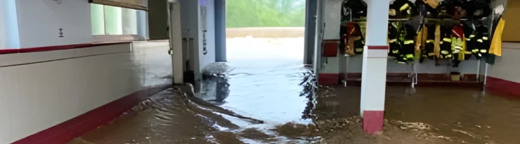
In many cases, nuisance alarms tie back to sensing or grounding circuits. For example, moisture in the starter enclosure can change resistance paths and create false signals. Also, degraded insulation can show up only when the system runs under load. As the run time increases, the fault becomes obvious, but the early clues matter.
Kord fire protection technicians often recommend routine checks of torque on power terminations and a careful look at cable routing. Because if the cable looks “fine” but it has worn insulation near an edge, it will not stay fine for long. The starter does not care about good intentions, only electrical integrity.
Patterns that help isolate intermittent faults
- Trips appear only during humid mornings or after washdown exposure
- Alarms occur during vibration or right after the pump room door is closed
- Faults happen after extended run time as components heat up
- Temporary resets work until another demand sequence begins
- Insulation tests or visual checks reveal damage near sharp cabinet edges
These patterns are useful because they turn an annoying mystery into a narrower test plan. Instead of waiting for the next random failure, technicians can reproduce likely conditions, monitor the right points, and catch the circuit misbehaving in real time. That is a lot better than standing in front of the cabinet hoping it confesses.
When inspection reveals overheating, moisture, or insulation damage
Overheating is one of the clearest warning signs. If the starter enclosure shows discoloration, burnt smell, or hot spots at terminals, the technician should treat it like a priority incident. They should inspect lug torque, verify conductor condition, and check for signs of arcing. Then, they should test insulation integrity according to the site procedures and applicable standards.
- Loose terminals cause high resistance and heat buildup
- Damaged insulation can create leakage paths and ground fault trips
- Moisture intrusion leads to corrosion and unstable control signals
- Ventilation or space heater settings may be wrong in cold climates
- Failed components inside the starter enclosure reduce performance over time
Next, the team should clean and dry the enclosure where permitted, replace compromised parts, and confirm the starter works under test conditions. Because “we will watch it” becomes “we will replace everything” later. And nobody wants that plot twist, unless they paid for the sequel.
This is also where preventive maintenance proves its value. A clean enclosure, verified torque, healthy insulation, and properly functioning heaters or ventilation can prevent a long list of future headaches. If your site already performs regular fire pump testing, starter inspections fit naturally into that rhythm and make the overall system far more dependable.
FAQ: Quick answers for fire pump motor starter issues
For anything beyond basic visual checks, a trained team should handle troubleshooting and testing with the site procedures and fire code requirements.
Final check and next steps with Kord fire protection
When fire pump motor starter issues show up, the fastest path to stability starts with a calm diagnosis, safe testing, and component level verification. Kord fire protection technicians trace the control command, confirm power quality, inspect contactor and overload behavior, and address heat or moisture clues before they grow. If your starter is locking out, tripping, or acting inconsistent, request a service visit now and schedule a documented troubleshooting plan. Protecting your pump is not a gamble, it is a process.
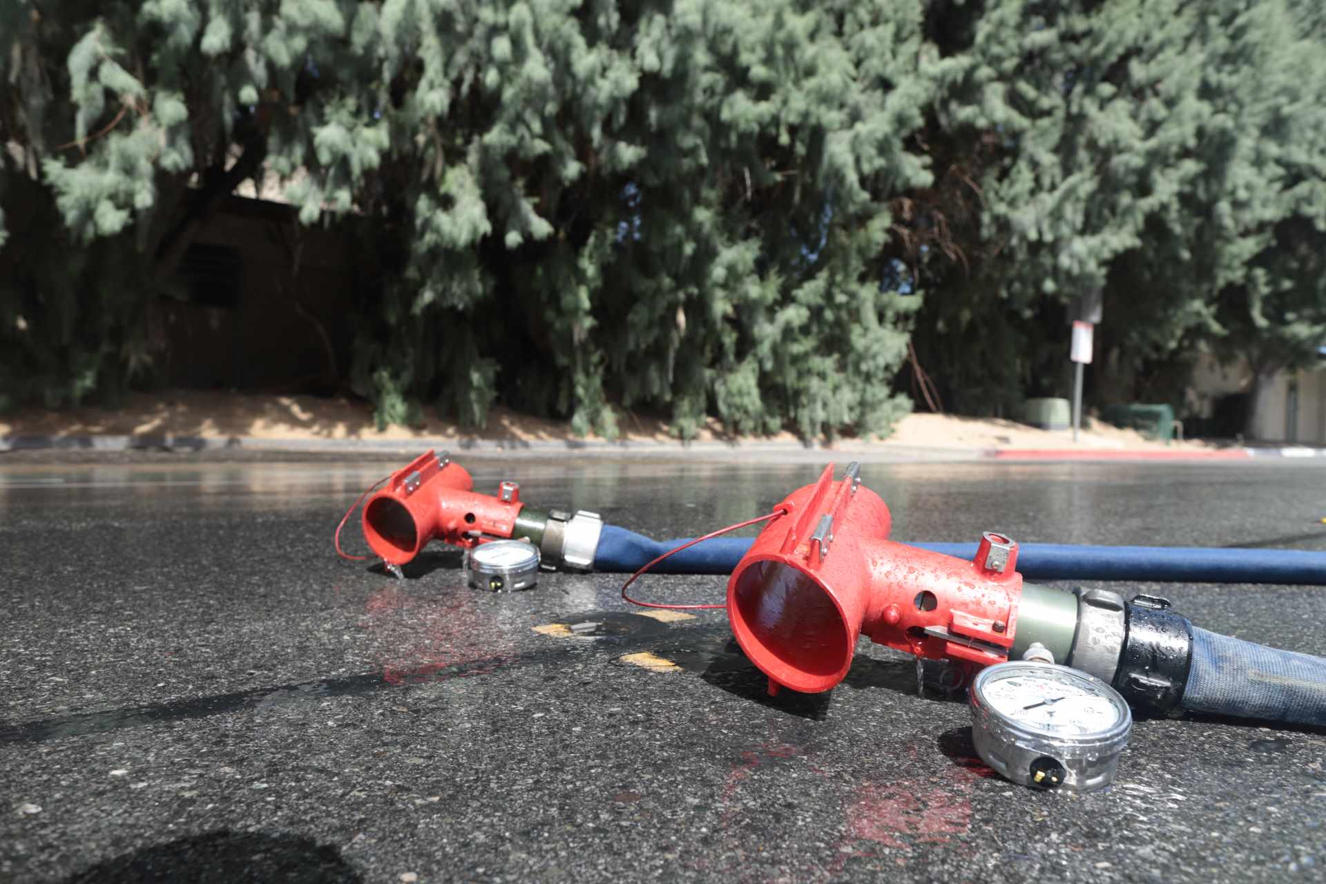
If you need broader support beyond the starter itself, Kord Fire also provides dedicated fire pump service for inspection, repair, and ongoing maintenance, along with fire alarm service to support the larger life safety picture. That combination helps keep detection, notification, and water delivery working together instead of leaving one critical piece to improvise under pressure.
Join Our Newsletter!
Get the latest fire safety tips delivered straight to your inbox From our Newsletter.