Commercial Fire Pump Controller Troubleshooting in Australia
Quick Answer: Commercial fire pump controller problems usually come from power issues, sensor wiring faults, bad contactors, or control circuit drift. A strong troubleshooting approach checks incoming voltage, output loads, alarm signals, and pump starter logic in a set order. For ongoing reliability across Australia, Kord Fire Protection can support commissioning, audits, and fast repairs.
Fire pump performance starts long before water flows. In the real world, it begins inside fire pump electrical control panels that monitor, start, and control the system when it matters most. When a commercial controller acts up, the site team needs answers fast and clear, not a mystery novel written in blink codes and burnt smell. This article walks through practical troubleshooting steps for common electrical issues in commercial fire pump controllers, plus how Kord Fire Protection becomes a vital partner for facilities, industrial sites, and retail operations across Australia.
For sites that want broader support beyond one fault callout, Kord Fire Protection also provides fire protection support for compliance and readiness across Australia, which fits naturally with controller servicing, documented inspections, and long term system reliability.
Common symptoms in commercial fire pump controllers
To troubleshoot properly, a technician first links symptoms to likely circuits. Therefore, the best results come from watching what the controller actually does during a test. Typical issues show up in several familiar ways. For example, the controller may fail to start the pump when commanded, it may drop out after a short run, or it may generate repeated trouble alarms. Sometimes it even “works” during tests but fails under real demand conditions, which is the electrical equivalent of a car that starts in the driveway and dies on the highway.
Common symptom patterns include the following:
- No start when the controller receives a start command
- Instant trips from overload or ground fault
- Phase loss or motor protection alarms
- Failed feedback signals that indicate wrong status from starters or pressure switches
- Intermittent operation that comes and goes like a pop song stuck in someone’s head
- Control voltage alarms that point to supply or transformer issues
Why symptom mapping matters before parts get blamed
This early symptom mapping prevents random component swapping, which is expensive, slow, and usually about as satisfying as replacing half a car because one dashboard light came on. A controller fault often looks bigger than it is. However, when the symptom is tied to a specific path such as supply, input, feedback, or starter output, the troubleshooting process gets much faster and much cleaner.
Power and control supply faults that stop starts
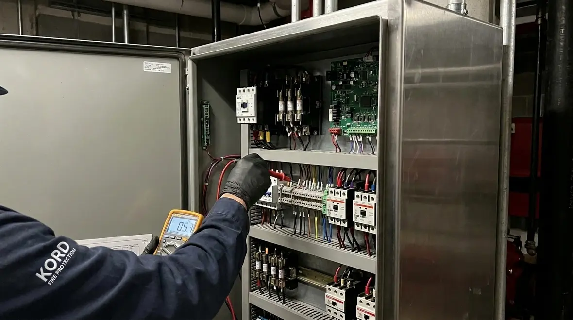
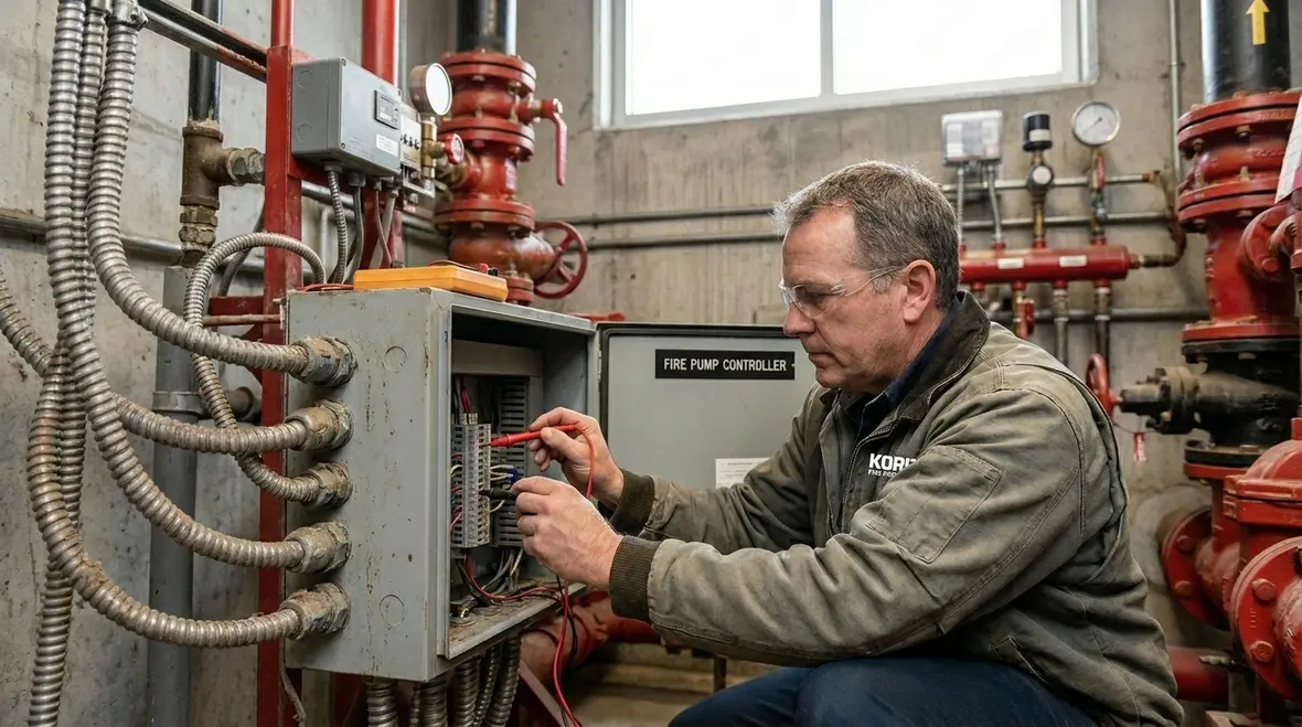
Before touching logic settings, the technician checks power. In most commercial installations, the controller relies on correct incoming supply, correct control voltage, and stable transformer outputs. If any of these fail, the control board can sit there looking innocent while it refuses to start. First, a person verifies incoming voltage at the controller terminals. Next, they check phase balance and contact points that can loosen over time due to vibration and heat cycling.
Then they look at control power. Many systems use a transformer, rectifier, and fuses to generate the board’s low voltage. If one fuse is open, the display may stay lit through some paths, but the outputs may never energise. Therefore, the checks should include:
- Incoming three phase voltage and frequency at the controller
- Voltage at the transformer primary and secondary
- DC supply for the logic and relay coils
- Fuse condition and continuity through control sections
- Loose wiring at terminal blocks and crimp quality in field wiring
Also, technicians verify the grounding and bonding path. A poor ground can create nuisance trips, erratic inputs, and unreliable relay feedback. Kord Fire Protection often helps teams because they treat power and control integrity as part of an ongoing compliance mindset, not a one off fix.
The supply side is boring until it ruins your day
That is why competent troubleshooting starts with meters and terminals, not assumptions. Incoming supply problems are not glamorous, and nobody is making an action movie about a loose terminal screw. Still, unstable voltage can create faults that imitate logic failures, bad outputs, and even false alarm states. When the power side is unstable, the rest of the controller has no fair chance to behave.
Input circuits, sensors, and feedback signals that confuse the controller
After confirming supply health, the next step targets the signals that tell the controller what to do. Fire pump control systems often use pressure switches, flow switches, tank level inputs, and starter feedback contacts. However, the logic only behaves correctly when these inputs match the expected states. If a pressure switch sticks, a wiring pair reverses, or a feedback contact fails, the controller may think the pump never ran, even though it did.
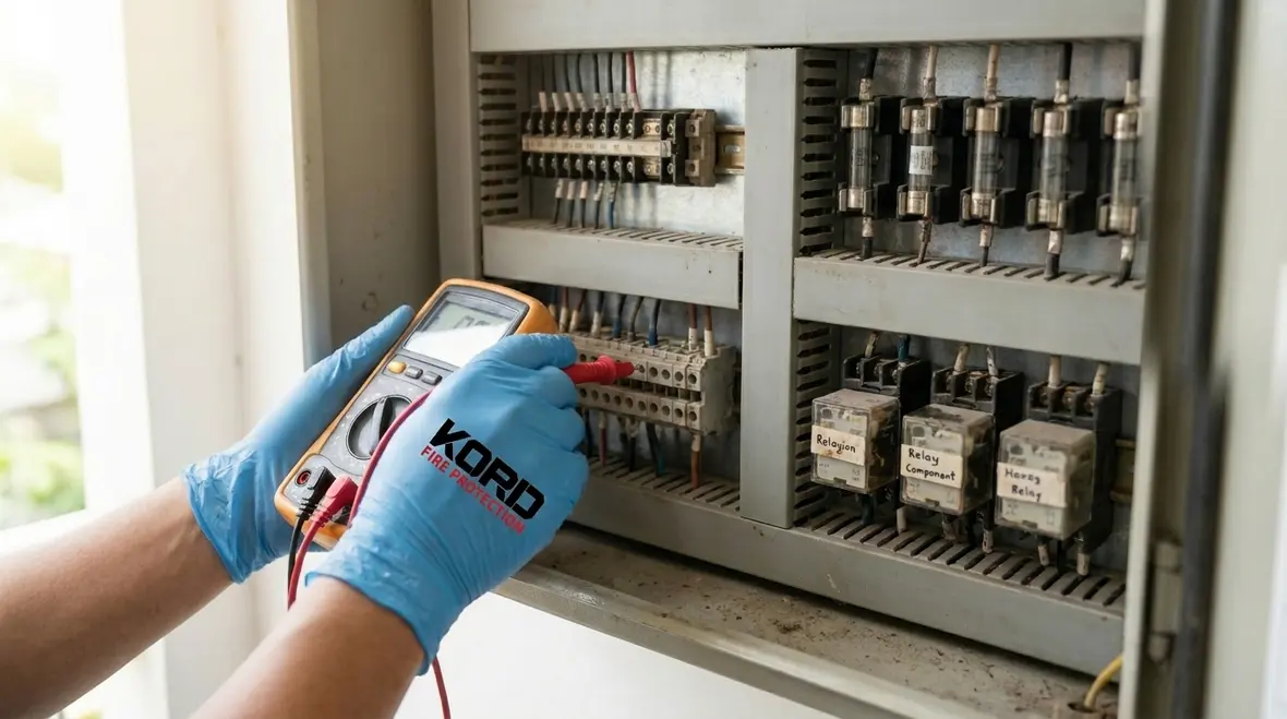
For troubleshooting, a technician isolates each input path and tests it methodically. First, they confirm wiring polarity and terminal identity. Next, they test the switch operation at the point of use, not just at the controller. After that, they confirm that the controller sees the input change on the screen or status LEDs. Transition matters here: the controller needs a clean signal edge, not a noisy one.
Key things to check include:
- Pressure switch contacts for correct cut in and cut out ranges
- Starter permissive and interlock switches
- Common faults like reversed leads at terminal strips
- Feedback contacts from motor starters and contactors
- Wiring segregation to prevent electrical noise intrusion
- Moisture ingress on conduit entry points
At this stage, a simple sarcasm moment is warranted: if a controller receives contradictory inputs, it will not “use common sense.” It uses logic. And logic, unfortunately, does not negotiate.
This is also where documentation earns its keep. As built drawings, terminal schedules, and prior service notes help separate original design intent from later field improvisation. Without them, a technician can spend a lot of time discovering that what should be on terminal twelve is now on terminal fourteen because someone, sometime, made a creative choice and then walked away from the scene.
Output sections, starters, and motor protection trips
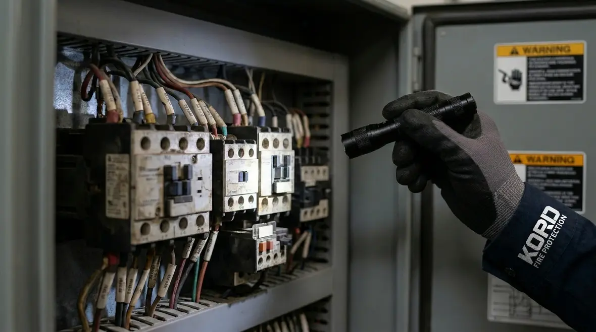
Once the controller understands the demand, it must energise the starter and hold the run command through the correct sequence. Problems often arise in contactors, motor starters, overload relays, and output relay contacts. Therefore, the technician must verify both electrical continuity and actual actuation. They also confirm that the motor protection settings match the pump motor characteristics.
Common issues include contactor coil failures, welded contacts, and overload relays tripping due to incorrect settings or reduced phase supply. In addition, a failing current transformer or incorrect wiring can cause false overload trips. So, the practical approach follows a chain: inspect, measure, test, then verify feedback.
Technicians typically:
- Inspect contactor and starter contacts for pitting or overheating
- Test coil voltage and control relay output
- Verify correct overload relay range and calibration
- Check current transformer wiring polarity and wiring integrity
- Measure motor current during trial runs and compare to nameplate
In facilities across Australia, these steps matter because heat, dust, and vibration can degrade components faster than many people expect. Moreover, a well kept controller avoids nuisance alarms that waste operational time and drain trust in the system.
When protection devices are right, they look invisible
Motor protection only gets noticed when it trips, which means it rarely gets applause for the days it quietly does its job correctly. Still, wrong settings, aging hardware, and poor wiring practices can turn legitimate protection into constant interference. Good troubleshooting proves whether the trip is responding to a real electrical condition or acting on bad information.
Control board drift, alarm logs, and test sequence checks
Many controller faults look electrical, but they are actually logic, configuration, or timing issues. Over time, setpoints can drift due to adjustment, replacement parts, or changes made during previous service. As a result, the controller might start too early, stop too late, or report alarms that do not match field conditions.
A careful technician reviews event logs and alarm history first. Then, they correlate timestamps with pump start attempts, phase events, and pressure changes. Transition words matter because sequencing is everything: if an output never gets the correct permissive, it will never start; if the pressure input lags, it may trip out. Therefore, a “works on the bench” system can still fail on site.
Practical tasks include:
- Review alarm and event history for patterns
- Verify settings like run time, reset logic, and phase fault behaviour
- Confirm that controller software version and board type match installation documentation
- Check terminal numbering against as built drawings
- Test the full start to stop sequence, not only the initial command
When teams want dependable outcomes, partnering with Kord Fire Protection helps because they align field troubleshooting with commissioning standards and operational documentation. In other words, they help the system behave the same way today as it will at the next inspection.
For readers wanting a related look at signal handling and response pathways, Kord Fire Protection also explains what fire alarm monitoring is and how it works, which fits naturally with understanding alarm signals, reporting flow, and dependable system behaviour when an event actually occurs.
How Kord Fire Protection supports reliable firefighting readiness
Controller repairs and troubleshooting fix the immediate problem, but reliability is a long game. Facilities, retail sites, and industrial operations need a partner who can support service schedules, component sourcing, and verification testing, especially when downtime creates real business risk. That is where Kord Fire Protection becomes a vital partner with this service job.
Kord Fire Protection can support through:
- Condition based service visits and practical inspection checklists
- Commissioning support after repairs or component replacements
- Documented test results and clear findings for facility managers
- Fast fault isolation during active trouble conditions
- Upgrades and component swaps that match controller and pump requirements
Also, because Australia covers diverse climates and site types, a partner with experience across environments helps reduce repeat failures. And nobody enjoys paying twice for the same issue, unless it is tickets to a concert. Fire pump electrical readiness deserves better than encore troubleshooting.
FAQ for fire pump controller electrical issues
Final call for troubleshooting and service
When a commercial fire pump controller shows trouble, the best move is swift, logical troubleshooting followed by verified testing. A reliable fix protects the pump, reduces nuisance alarms, and keeps compliance on track. Strong process matters because guessing at faults usually costs more time than measuring them properly in the first place.
If the site needs expert support across industrial, retail, and facilities environments in Australia, contact Kord Fire Protection for controller troubleshooting, commissioning support, and dependable service planning. They will help the system perform when it counts.

Join Our Newsletter!
Get the latest fire safety tips delivered straight to your inbox From our Newsletter.