Standpipe System Electrical Needs for Booster Pumps
Electrical design basics for standpipe booster pump performance
Modern standpipe booster pumps work like the unsung heroes of fire protection. When a fire happens, they must deliver water fast, reliably, and within strict timing. That means the standpipe system electrical needs start long before the pump ever turns on. In the real world, the design team chooses the right voltage, provides the correct starting method, and protects every circuit so the pump keeps running when the building needs it most. And because conditions vary, the electrical plan must match the pump duty point, the wiring length, the site power quality, and the fire alarm and emergency power strategy. To make sure this doesn’t become a “trust me, it will be fine” situation, kord fire protection technicians often explain requirements in plain language, walking people through what to check and why it matters.
The first job of the electrical design is to keep the pump operating at the required flow and pressure. However, electrical power does not just mean “getting electricity to the motor.” It means giving the motor a stable supply so it reaches speed without nasty voltage dips, nuisance trips, or slow starts. In addition, the electrical plan must account for the pump controller, any soft start or VFD equipment, and the status and supervision devices that feed back to the building fire system.
When kord fire protection technicians review power design, they usually focus on three practical realities. First, the motor nameplate does not automatically match site conditions. Second, long cable runs create voltage drop, which can reduce torque and prevent proper acceleration. Third, the protection scheme must survive a fire event, not just look good in a binder. After all, a system that fails during a test is like a smoke detector that only works when you dust it. Sure, it’s something, but it’s not the point.
Standpipe system electrical needs: voltage, amperage, and starting method
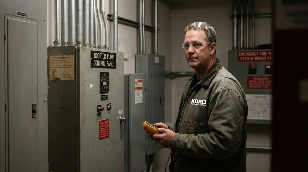
The standpipe system electrical needs depend on the pump motor rating and the starting method. Motors may require single phase or three phase power, commonly with specific voltage standards based on the site. Then the system design adds the operating current and the starting current. Starting current matters because many motors draw several times their running current when they accelerate.
If the system uses a direct-on-line start, the electrical supply must handle the inrush without causing a harmful voltage dip. If the system uses a soft starter or a variable frequency drive, the controller changes the starting profile, often reducing inrush while controlling acceleration. Yet the drive must still meet code requirements for fire pump or standpipe pump operation, including supervision and continuity during demand.
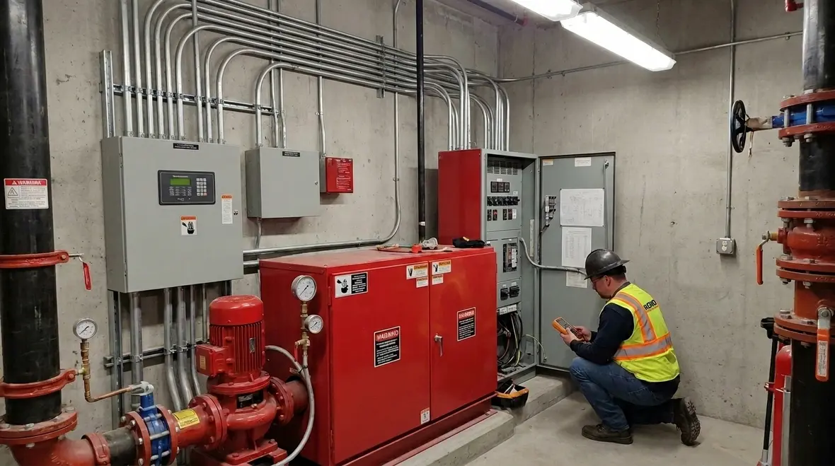
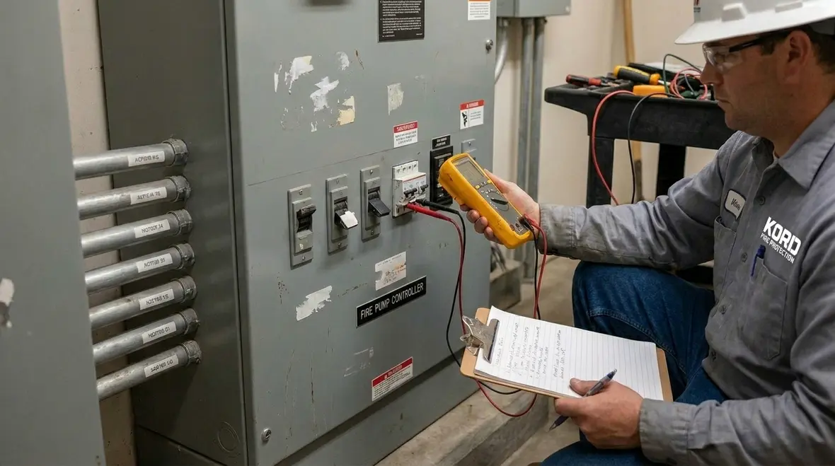
To keep things clear, kord fire protection technicians typically ask teams to confirm the following before they finalize drawings: motor full load amps, locked rotor amps, controller input requirements, and any required minimum voltage during start. They also check the conductor sizing method and confirm that the control cabinet does not introduce new failure points. In other words, the electrical design must be coordinated, not just assembled.
Emergency power and reliability expectations during a fire
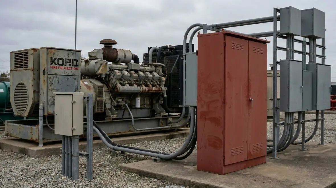
Modern installations increasingly rely on emergency power sources to keep pumps running even when normal utility power fails. Therefore, the electrical plan must define how the standpipe booster pump system interacts with generators, transfer switches, and any supervised emergency distribution panels.
In many buildings, the system requires a specific transfer time, and the generator must maintain voltage and frequency within a tolerance that the drive and motor can accept. Also, the starting sequence must consider load pickup. If the facility starts multiple motors at once during an outage, the generator can struggle. Consequently, designers may include sequencing logic or staggered start times, while still meeting fire performance requirements.
kord fire protection technicians often explain reliability in terms of “don’t make it complicated during the worst minute of the job.” They review how the transfer switch handles bypass or maintenance positions, how the emergency panel is supervised, and how the controller behaves when power returns. Even small control misbehavior can cause a pump to stall or reset at the wrong moment. And nobody wants that plot twist, not even if it’s a streaming series with six seasons and a cliffhanger.
Cable sizing and voltage drop in real installations
Engineers and electricians often focus on conductor ampacity, which is necessary, but not always sufficient. Next comes voltage drop, especially when cable runs span mechanical rooms, risers, and multiple floors. When voltage drops too far, the motor cannot develop enough torque to accelerate properly. Then the pump may fail to reach required speed, and the system can trip protection devices.
To address this, designers calculate conductor size using length, material, temperature rating, and load current. Then they apply an allowed voltage drop limit based on the design standard and motor starting method. For variable frequency drives, current draw can vary, so designers must verify voltage and current performance during acceleration and steady state.
In addition, electricians must ensure terminations stay tight and correct. Loose connections create heat, and heat creates resistance. Over time, that resistance can turn a good design into a problem that shows up during the next inspection cycle. So kord fire protection technicians recommend practical checks: confirm proper cable type, verify end preparation, and document torque values. It’s not glamorous work, but it prevents the kind of failure that makes maintenance staff invent new swear words.
Overcurrent protection, disconnects, and coordination
Protection devices must stop short circuits and faults without nuisance trips during normal demand. That requires careful coordination between breakers, fuses, starters, and the pump controller. If protective settings are too tight, the system may trip at a time when the fire scenario demands continuous operation.
Designers generally choose overcurrent devices based on motor characteristics, controller recommendations, and code requirements. For example, a motor circuit breaker must support motor starting current profiles, and a controller must be compatible with the selected device trip curves. Then the electrical distribution upstream must also coordinate so that a fault isolates correctly without disabling unrelated equipment.
kord fire protection technicians typically encourage teams to think of protection as a layered defense. They check that the disconnect location allows safe service while also meeting access and labeling needs. They also verify that the system supervision signals connect to the fire alarm or monitoring panel in a way that stays reliable. If the alarm cannot detect a controller fault, the facility will not know it is losing protection until the emergency arrives.
Control power, supervision, and instrumentation that prevents surprises
Motor power is only half the story. Booster pumps also need control power for the controller logic, sensors, valves, and interface signals. Therefore, the standpipe system electrical needs include low voltage circuits that operate relays, switches, and status points. Control power failure can stop pump operation even when the main motor circuit seems fine.
Common control elements include pressure switches, flow switches, status feedback, and any fire alarm interface contacts. Additionally, the controller may include phase loss detection, overload supervision, and interlocks for required valve positions. Each of those inputs and outputs must function correctly under emergency conditions.
Here is where kord fire protection technicians add value. They often verify supervision wiring against the intended monitoring points. They check that each critical condition reports correctly, such as pump running, pump fault, phase failure, and controller trouble. They also review whether the system resets as intended after an emergency power event. In short, the electrical plan should not just start the pump; it should help the facility understand the system state before, during, and after a demand.
Installation testing, labeling, and maintenance-friendly documentation
After design and installation, teams must test the system in a way that verifies both electrical and operational performance. That includes verifying correct rotation, confirming phase balance, checking controller operation, and ensuring the protective devices behave as designed. It also includes checking that the emergency transfer sequence works as expected and that supervision signals report to the right location.
Labeling matters more than people think. Clear labeling helps maintenance staff isolate circuits and find the right equipment during repairs. It also helps inspectors confirm that the system matches the submitted documents. Therefore, technicians and electricians should document breaker IDs, conductor identification, panel schedules, and any controller settings that impact operation.
kord fire protection technicians often recommend building a simple test checklist that aligns with the actual job site. Then the team uses that checklist every time. Consistency reduces errors, and it also makes it easier to spot trends, like recurring voltage drop issues at a specific cable run or nuisance trips tied to a controller setting. Nobody wants surprise failures, especially not the kind that arrive like a pop-up ad at the worst possible moment.
FAQ about electrical requirements for standpipe booster pumps
Call to action for a safer, code-ready power plan
Electrical power for modern standpipe booster pumps must stay dependable when conditions get ugly. If the design team wants fewer surprises, the next step is a focused review of motor ratings, starting method, conductor sizing, emergency power behavior, and supervision wiring. Schedule a consultation with qualified kord fire protection technicians to confirm the standpipe system electrical needs align with real site conditions and test expectations. Start now, test properly, and keep the system ready to perform. After all, in a fire, confidence should not be a hope.
Next step
What to double-check first
Confirm motor nameplate requirements, locked rotor amps, and the selected starting method. Then verify conductor sizing and voltage drop for the real cable run lengths. If you’re using emergency power, make sure transfer and sequencing behavior matches the generator’s limits.
Why it matters
Because the real test is not the binder review. It’s when the system has to deliver water fast and stay running. A coordinated electrical plan helps prevent trips, stalls, and surprises during the demand.
Know Your Weapon Before You Fight the Flame
Kord Fire Protection is your go-to when it comes to all things fire protection. For over 20 years, we’ve been serving Southern California with the quality service and equipment to keep your home or business safe at all times. Our competitive prices reflect our unwavering commitment to protecting what matters most in the event of a fire emergency. Give us a call, send an email, or use that form!

Join Our Newsletter!
Get the latest fire safety tips delivered straight to your inbox From our Newsletter.