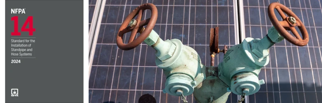
NFPA 14 Section 10.4: Sizing Pipe to Deliver the System Demand
Quick Answer: NFPA 14 Section 10.4 requires the system piping for a standpipe to be sized so the most demanding outlet and hose stream can be delivered at required pressure and flow, while accounting for friction loss, elevation changes, valves, fittings, and net pressure at the highest demand point.
For a practical next step, facilities managing standpipe performance can also review Kord Fire Protection’s fire protection services in Southern California to connect inspection, testing, repairs, and documentation support with real building conditions.
Why NFPA 14 Section 10.4 pipe sizing determines real-world performance
Standpipe systems fail at the worst time when the hydraulics do not match the field conditions. NFPA 14 Section 10.4 focuses on getting the right flow and pressure at the end use point by sizing the piping and system components to deliver the calculated system demand. In practical terms, standpipe pipe sizing for system demand is the process of selecting pipe diameters and designing the route so the system can overcome friction loss and pressure reductions through the standpipe, hose valves, hose, and accessories.
Commercial, industrial, and retail facilities often face additional complexity: frequent renovations, variable ceiling heights, multiple risers, unusual mechanical room routing, and aging valve trains. These realities make compliance-driven pipe sizing and ongoing maintenance essential, not optional.
What Section 10.4 requires, in operational terms
Section 10.4 is about hydraulic delivery. The system must be able to supply the required flow rate and pressure at the point of use that represents the worst-case demand. The pipe size choices control how much pressure remains after overcoming system losses.
From a design and inspection standpoint, the key operational expectations include:
- Hydraulic calculations align with demand points, including the most remote outlet and the required hose stream conditions.
- Friction loss is calculated across the actual piping configuration, including length, fittings, and hose valve assemblies.
- Elevations are handled correctly so static pressure and available residual pressure do not drop below requirements at the demand outlet.
- Component losses are not ignored, especially at valves, check valves, elbows, reducers, and standpipe connections.
Common field compliance challenge: the as-built piping often differs from the drawings used for original calculations. A reroute around equipment, a replaced valve with a different pressure loss profile, or a change in hose valve assembly can shift friction loss enough to reduce delivered pressure.
How hydraulic demand drives standpipe pipe sizing
Step one: identify the system demand point
Pipe sizing begins with the outlet that produces the highest hydraulic penalty. That typically means the most remote location, the highest elevation, or the combination that generates the greatest total loss from the source to the nozzle.
Step two: calculate pressure available at the source and remaining at the outlet
The design must ensure the available pressure at the standpipe connection is sufficient after accounting for:
- Friction loss in straight pipe driven by flow velocity and pipe diameter.
- Friction loss in fittings, including elbows, tees, reducers, couplings, and drain valves.
- Loss across valves, including control valves, check valves, and any devices that introduce measurable pressure drop.
- Elevation change from the source to the discharge point.
- Any hose and nozzle requirements that affect the discharge pressure and stream characteristics.
Because friction loss increases quickly as pipe diameter decreases, undersized piping can produce a cascading failure: reduced hose stream pressure, poor discharge reach, and ineffective cooling or suppression. This is why standpipe pipe sizing for system demand must treat the system as a hydraulic network rather than a collection of nominal pipe sizes.
Common design and field pitfalls that lead to noncompliance
1) Using outdated layouts for the hydraulic calculation
Renovations often introduce changes: additional risers, altered routing, or new partitions that require rerouting. If the hydraulic calculation uses the original layout, Section 10.4 sizing can become inaccurate.
Maintenance takeaway: Facilities should maintain “as built” hydraulic data and route maps so the design basis matches reality. Kord Fire Protection supports commercial compliance by helping track configuration changes and aligning documentation with field conditions.
2) Ignoring pressure loss at valves and hose station components
Valves can add significant friction loss depending on their type, internal geometry, and condition. A valve that was originally specified may be replaced with an equivalent by appearance, but not by pressure loss. This small change can materially affect delivered pressure at the demand outlet.
3) Overlooking partial obstructions and aging effects
Deposits, corrosion, debris in strainers, and internal scale can reduce effective flow area. Even if pipe diameter remains the same, the hydraulic performance changes. This failure mode often emerges during operational testing, when delivered pressure no longer matches the original design assumptions.
4) Mismanaging elevation and floor transitions
Misinterpreting source elevation, standpipe rise elevation, or outlet elevation can lead to incorrect static pressure and residual pressure outcomes. In multi level commercial facilities, this error becomes more likely when documentation is incomplete.
Inspection, testing, and documentation practices that keep sizing valid
NFPA 14 compliance does not end at design. Pipe sizing for system demand must remain true during operations, maintenance, and reinspection cycles. Practical programs include:
- Verify hose valve and hose connections function correctly and remain compatible with the calculated hose streams.
- Perform flow and pressure tests using procedures aligned with the applicable inspection and testing requirements, and compare results against design expectations.
- Document changes to pipe routes, valves, hose stations, and any components that affect pressure loss.
- Maintain clear access to the standpipe system so field conditions match the assumptions in calculations.
For related guidance on system design, hazards, and operational readiness, Kord Fire Protection recommends reviewing this resource: NFPA 14 safeguarding against fire hazards with standpipe and hose systems.
How Kord Fire Protection supports Section 10.4 compliance in commercial facilities
Commercial and industrial buildings need systems that perform under stress. Kord Fire Protection helps facilities manage the compliance lifecycle that standpipe pipe sizing for system demand requires, including ongoing inspection readiness, maintenance planning, and documentation support that reflects the as built system.
Common service value includes:
- Reviewing system configuration for hydraulic impacts after renovations.
- Supporting test planning that checks delivered pressure and flow against system demand assumptions.
- Identifying component issues that can change friction loss, such as valve condition and accessible hose station equipment.
This approach reduces the risk of “paper compliant” systems that do not meet performance requirements during actual operation.
Frequently Asked Questions
Conclusion and call to action
Accurate standpipe pipe sizing for system demand is not a one time design task. It must remain valid through renovations, component replacements, and maintenance condition. Facilities should verify that the as built configuration matches the hydraulic basis and that testing results support the pressure and flow requirements at the demand outlet. Engage Kord Fire Protection to help manage compliance, inspection readiness, and performance verification for standpipe systems under NFPA 14.

Join Our Newsletter!
Get the latest fire safety tips delivered straight to your inbox From our Newsletter.