NFPA 20 Chapter 6 Centrifugal Fire Pump Installation Requirements
Quick Answer: NFPA 20 Chapter 6 covers centrifugal fire pumps and the installation details that make them reliable. In Australia’s industrial, retail, and facilities environments, common issues like suction problems, misalignment, and valve setup can delay fire flow. Kord Fire Protection helps teams prevent these failures before commissioning.
NFPA 20 Chapter 6 sets the pace for centrifugal fire pump installation requirements by demanding proper pump selection, correct piping, and clean, verified commissioning steps. In the real world across Australia, those requirements do not stay “on paper.” They show up on site, where suction conditions, valve placement, base alignment, and power reliability either support dependable fire flow or quietly sabotage it. And yes, sometimes the pump runs perfectly in testing while still underperforming during an actual emergency, because the setup and acceptance steps were treated like a casual checklist. Kord Fire Protection steps in early to keep centrifugal systems from turning into that kind of “surprise party” no one asked for.
For teams that want broader support beyond the pump itself, Kord Fire Protection also provides full fire protection services that connect inspection, repair, testing, and system readiness into one practical program.
Why NFPA 20 Chapter 6 matters for centrifugal pumps
NFPA 20 Chapter 6 focuses on the behaviour and installation of centrifugal fire pumps so the system can deliver required flow and pressure under fire conditions. Centrifugal pumps depend on stable suction, correct operating speed, and proper hydraulic conditions. If installation reduces net positive suction head available, the pump can cavitate, lose pressure, or become inconsistent. As a result, the fire pump may still “start,” but it might not perform the way the hazard assessment expects.
In facilities across Australia, that performance gap can matter in a hurry. A loading dock with fast-growing heat release, a retail tenancy with complex egress routes, or an industrial process line that adds obstruction and demand pressure all increase the pressure to get installation right the first time. Kord Fire Protection treats the pump room as mission control, not a storage closet for spare bolts.
Common suction and piping mistakes that derail performance
Most failures trace back to suction and piping, not the pump itself. Even when the pump is selected correctly, installation can choke it. Therefore, the team must check every connection, every fitting, and every change in direction. A few typical troublemakers include:
- High suction losses caused by undersized suction piping, excessive elbows, or poorly routed pipework
- Air ingestion from suction leaks, loose flange joints, or incorrect venting
- Incorrect strainers and obstructions that restrict flow and shift the operating point
- Improper pipe support that forces the pump to “fight” the alignment during start and stop cycles
In many installations, teams rush through the suction line because it looks straightforward. However, suction conditions drive NPSH margin. Moreover, once cavitation starts, it can damage impellers, seals, and bearings while also reducing delivered pressure. It is a double hit: the system underperforms and hardware ages faster than it should.
As a practical tip, Kord Fire Protection often encourages a pre-commission review of suction drawings against installed field conditions, so the final checks do not reveal “surprises” like a valve installed where the design intended an unobstructed path. Nobody enjoys rewriting commissioning reports at the last minute, especially when the fire authority prefers clarity over guesswork. And yes, guesswork is not a testing standard. Not even in pop culture.
Where better interlocks save time later
If your project team is mapping this work against the wider standard, it helps to also review how NFPA 20 regulates fire pump systems so installation details, acceptance expectations, and long-term compliance all stay connected instead of living in separate binders that only meet during audits.
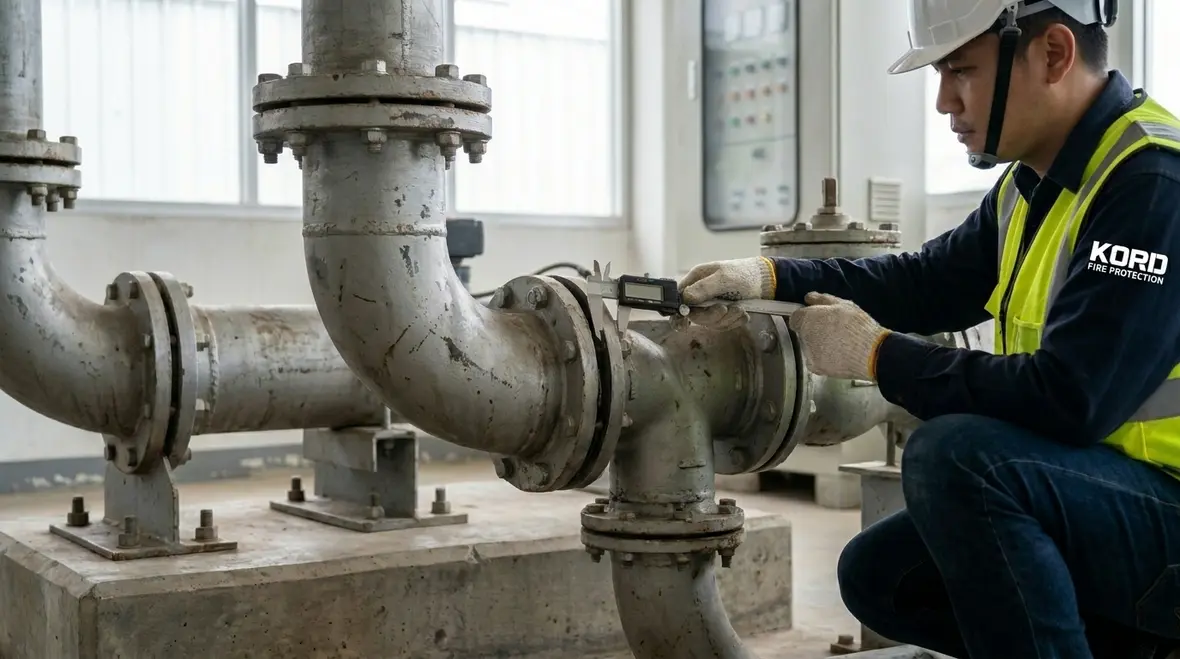
Alignment, base mounting, and vibration issues in pump sets
Even well-planned piping can lose its advantage when alignment and base mounting are off. If the pump and driver do not align within required tolerances, the system can experience vibration, seal wear, and unreliable coupling performance. As a result, maintenance schedules expand, and emergency readiness declines.
Key installation points typically include:
- Correct base preparation and grouting practices that keep the pump stable under load
- Coupling alignment verification using proper methods before commissioning
- Flexible connections where required, without turning the system into a wobble machine
- Solid foundation support to prevent piping forces from loading the pump
For facilities, this matters because vibration can also affect nearby equipment and cabling. In some pump rooms, technicians notice a “harmless shake” during start-up, then later chase mysterious seal leaks. By then, the root cause often came earlier. Kord Fire Protection focuses on the fundamentals at the installation stage so the pump room behaves like a well rehearsed play, not like a sitcom where everyone keeps missing their cue.
Valves, controls, and electrical reliability during commissioning
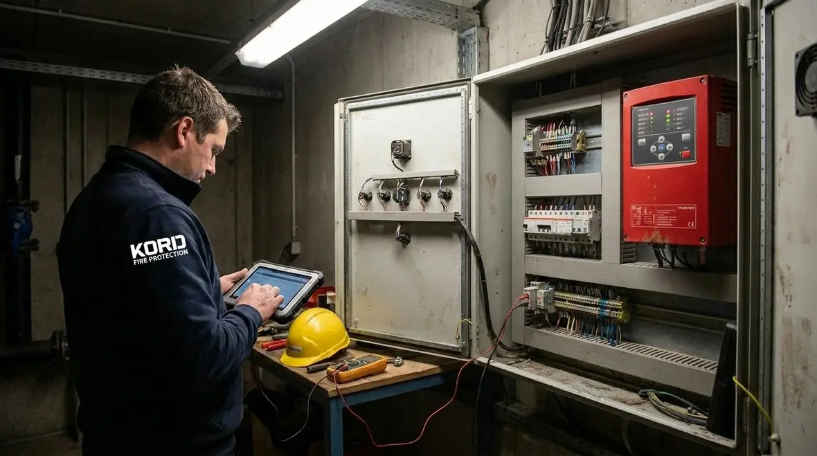
NFPA 20 Chapter 6 also expects controls and electrical arrangements that support dependable operation. Therefore, the installation must include the correct valve positions, proper interlocks, and tested starting sequences. A centrifugal fire pump cannot deliver its promise if the control logic blocks a start or if a supervisory signal masks a real fault.
Common installation issues include:
- Mispositioned valves on suction or discharge that limit flow during operation
- Incorrect check valve setup that causes water hammer or backflow concerns
- Wiring errors in start, stop, and auxiliary contacts
- Control settings drift because of rushed calibration or undocumented changes
Commissioning becomes the line that separates “installed” from “ready.” During this phase, the team verifies flow, pressure, starting sequence, and alarms. Meanwhile, they confirm that the pump operates at the intended speed and that controllers respond the way the system design requires. Kord Fire Protection adds value by coordinating commissioning steps with the wider fire protection program so the pump set works as part of the whole system, not as a lone actor trying to carry the entire movie.
How pump room conditions affect delivered fire flow
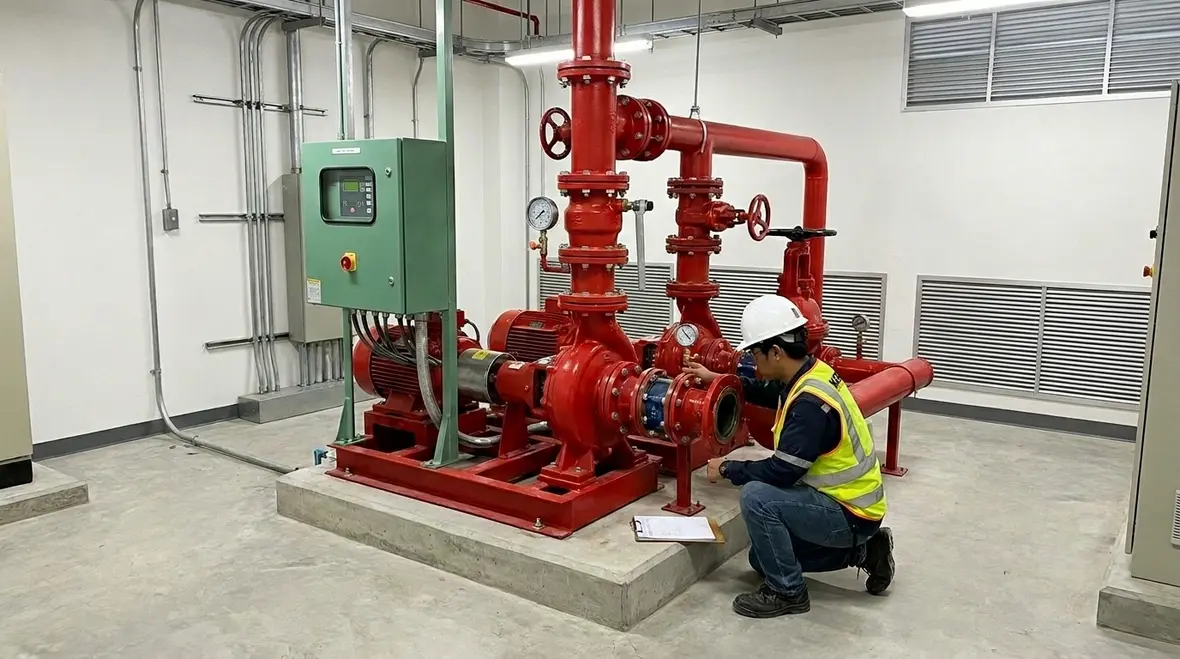
Installation quality does not end at the pump and piping. Pump room conditions influence how the system behaves. For example, excessive heat, poor ventilation, water ingress, or blocked access can cause control issues or delay response during emergencies. In busy industrial sites and multi tenancy retail centres, pump rooms sometimes get treated like back-of-house storage, and that never ends well.
To support stable operation, the team should manage:
- Ventilation and ambient temperature around controls and drivers
- Drains and moisture control to prevent corrosion and electrical risks
- Clearances for safe testing, maintenance, and access
- Protection of components against impact and accidental dislodgement
When these items receive attention, commissioning tests produce consistent results. Conversely, when pump room conditions fluctuate, technicians see “inconsistent” outcomes and end up chasing symptoms rather than fixing the causes. Kord Fire Protection helps facilities maintain disciplined pump room standards, so the system behaves predictably when it matters.
Documented acceptance: proving the system meets the requirements
People often treat acceptance like paperwork, but it is actually evidence. NFPA 20 centred acceptance supports reliability because it records what the system can do and under what conditions. Therefore, the installation team must document results clearly, align field work with the design intent, and correct issues before final handover.
A strong acceptance approach typically includes:
- Hydraulic test evidence showing flow and pressure behaviour at required conditions
- Verification of sensors and alarms to ensure supervisory signals work as intended
- Control sequence checks for auto start, shutdown, and fault response
- As built drawings that match what actually sits in the pump room
And yes, the best time to fix a valve mistake is before the “final” test. Once the certificate chase begins, the schedule tightens like a fast moving train, and nobody wants to be the passenger holding the wrong ticket. Kord Fire Protection supports this stage by coordinating the technical work with the documentation needed for trust, compliance, and operational certainty.
FAQ
Need a partner who treats the pump room like critical infrastructure?
When a centrifugal fire pump installation is done fast but not verified deeply, the site pays later with unreliable performance and expensive corrections. Kord Fire Protection helps industrial, retail, and facility teams plan the work, prevent common installation issues, and complete commissioning with solid documentation.
If this job is on the horizon, reach out to Kord Fire Protection and lock in a system that stands up when it matters most. The goal is simple: dependable fire flow, fewer commissioning surprises, and a pump room that acts like critical infrastructure because, frankly, it is.

Join Our Newsletter!
Get the latest fire safety tips delivered straight to your inbox From our Newsletter.