Relief System Design Requirements for Ventilation Australia
Quick Answer: A strong relief and ventilation system design follows recognized engineering practices, then matches the risk profile of each Australian facility. It controls pressure, manages smoke movement, and supports safe egress and operations. When properly engineered, it reduces equipment stress, downtime, and safety exposure. Kord Fire Protection can guide approvals and fire-linked coordination.
In Australia, facilities rarely fail because someone “forgot” the relief system. They fail because the design never fully met relief system design requirements the first time, or because later changes pushed performance out of spec. Early planning must align relief sizing, ventilation balance, and operational reality. This means recognized engineering practices: clear design basis, code-aligned calculations, functional testing strategy, and a documented path from hazard assessment to final drawings and commissioning. Then, the team must coordinate with fire protection so smoke and fire behavior do not get treated like separate universes.
And yes, people sometimes treat smoke like it will follow the rules out of politeness. It won’t. So the design has to earn that trust with disciplined engineering.
Near the top of the planning process, teams often benefit from coordinating the ventilation concept with broader fire protection support in Australia, especially where smoke movement, alarms, and system approvals need to behave like one strategy instead of three separate opinions. For projects that require reference documentation during coordination, teams can also review California Title 19 as part of broader technical discussions.
Build the design basis like a pro, not like a guess
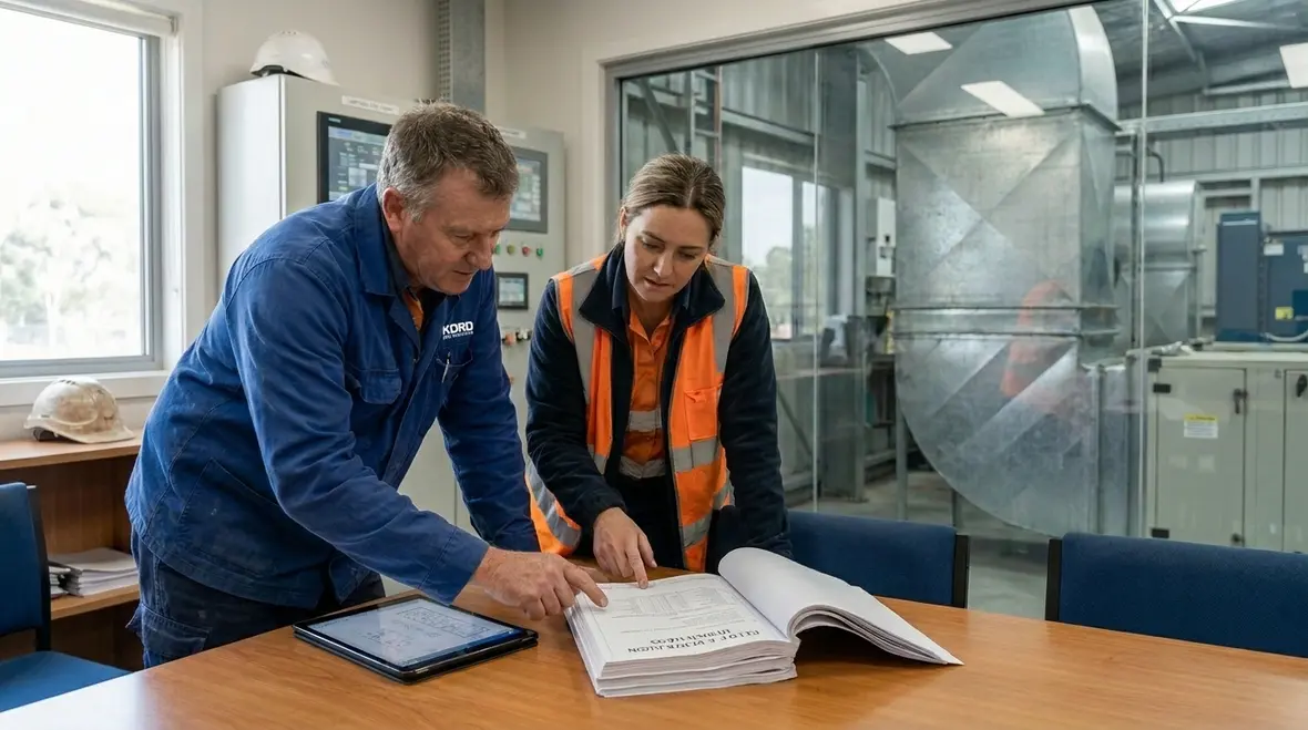
In this phase, the design team starts with the facts that actually drive a relief and ventilation system. They define the intended function, such as limiting overpressure in plant areas, controlling airflow during abnormal events, and supporting safe building conditions for occupants and responders. Next, they identify credible scenarios, including process upset, blocked flow, fire smoke influence, and maintenance states that change airflow paths. Then they set performance targets, such as maximum allowable pressures, acceptable exhaust rates, and time based activation expectations.
To meet recognized engineering practices, the design basis must also include assumptions, boundaries, and interfaces. For example, a facility may have multiple zones, shared ducts, dampers, smoke control routes, and emergency power constraints. If the design basis does not map those interfaces, the final system behaves like a well educated but uncoordinated team. Everyone shows up, but the goal still gets missed.
What belongs in the design basis document
A solid basis document usually spells out occupancy use, enclosure volumes, likely pressure events, ventilation modes, power dependencies, control philosophy, and the exact interfaces with other life safety systems. It should also identify who owns each decision. That matters because relief design problems love ambiguity. If nobody owns the boundary between HVAC behavior and fire response, that boundary turns into a surprise later.
How pressure relief sizing and airflow balance work together
Once the basis is set, the team sizes relief pathways and ventilation components to behave predictably under abnormal conditions. They calculate relief capacity based on system geometry, flow resistance, and required mass balance. Then they verify that relief does not simply “dump” the problem into another location. Instead, it should relieve pressure where the structure and protective systems can tolerate it.
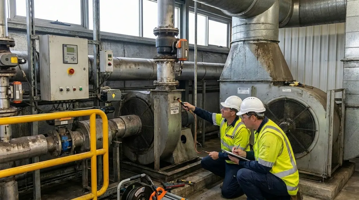
At the same time, ventilation balance must remain coherent. Ventilation does not just move air; it controls pressure relationships between spaces. Therefore, designers coordinate supply and exhaust so the system supports the intended pressure gradient without creating harmful backflow or spreading smoke. Where dampers, fans, and duct runs connect across zones, the design must include failure modes, including stuck dampers, fan trip scenarios, and power loss behavior.
In commercial and industrial facilities, this is where projects often get spicy. A minor duct routing change during fitout can alter resistance and timing. Consequently, designers keep design intent tight, and they document allowable changes. If someone tries to “value engineer” the duct thickness down to something that looks like it belongs in a snack package, the design must still hold.
Why balance matters beyond the numbers
Pressure relationships shape how smoke, heat, and contaminated air migrate through a building. A relief opening that is mathematically correct but operationally awkward can still cause trouble if it compromises another zone. That is why the team checks both calculations and real pathways. Air, unlike meeting agendas, tends to go where resistance is lowest and drama is highest.
Use recognized engineering practices for activation, control, and sequences
A relief and ventilation system only performs when it activates correctly. So the design team defines control logic, sensor placement, control setpoints, and fail safe behavior. They integrate interlocks that prevent conflicting actions, such as supplying air while exhausting in a way that defeats the relief goal. Then they establish sequences for normal operations and abnormal states.
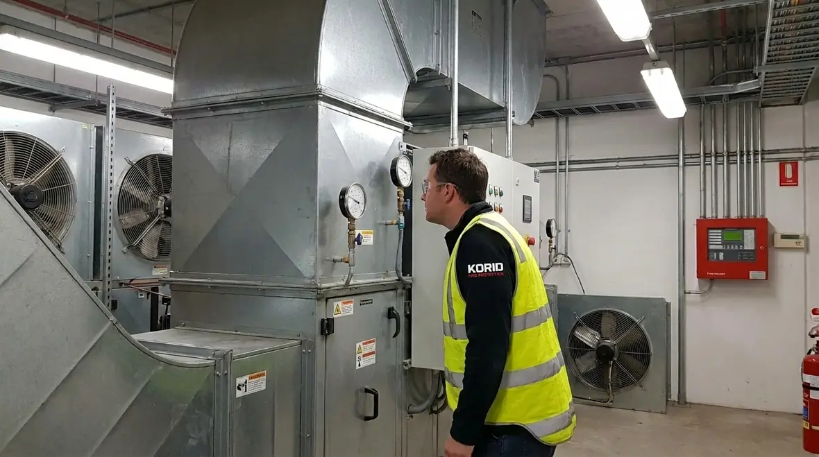
In facilities across Australia, the design often includes time delays, step responses, and alarm thresholds. Additionally, the team considers commissioning and testability from the start. For example, they plan how to verify damper travel, confirm fan start and speed, and validate pressure response curves. They also specify manual overrides and emergency operation pathways so the system can support operations under real conditions.
And because Murphy is always on the payroll, the design must include realistic scenarios such as partial blockages, varying weather effects, and maintenance modes. This helps ensure the system does not only work on paper, but also during the messy moments that actually matter.
Control sequences should be readable, testable, and boring in the best way
A good sequence narrative is not theatrical. It is clear enough that engineers, installers, commissioning agents, and facility staff can all follow it without decoding a mystery novel. Inputs, outputs, timers, overrides, alarm states, and fail positions should be obvious. If a sequence requires interpretive dance to understand, it is not ready for site.
Coordinate fire-linked performance instead of treating fire like a separate project
This is where Kord Fire Protection can become a vital partner with this service job. Relief and ventilation designs influence smoke movement, tenability, and how fire protection systems interact with the building’s airflow behavior. Therefore, the fire protection team must review and coordinate the ventilation and relief intent, especially where smoke control interfaces, fire dampers, and emergency ventilation overlap.
When Kord Fire Protection joins early, they help align protection strategies so relief actions do not undermine containment. For instance, designers must ensure relief exhaust paths do not pull smoke into protected escape routes. They also need to coordinate with fire damper schedules, fire alarm inputs, and any required fire engineered pathways. In short, fire protection input helps validate that the system supports safety goals rather than accidentally rewriting them.
For industrial, retail, and commercial facilities, this collaboration reduces the chance of costly rework during compliance review. It also helps teams present a consistent design story to stakeholders, including asset owners, consultants, and certifiers. For related technical context, Kord’s Fire Suppression Pressure Relief Function Guide pairs naturally with this topic because it explains how pressure control supports fire suppression performance when discharge events stress the enclosure.
Prepare commissioning and maintenance so the system stays in spec
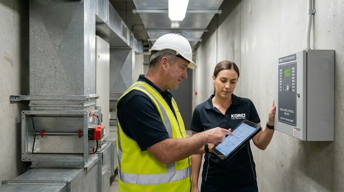
After installation, relief and ventilation systems require verification that matches the original engineering intent. Commissioning should check functional performance, calibration accuracy, and correct sequence execution. Engineers verify pressure response behavior against predicted curves and confirm that control logic produces the planned response for each scenario.
Then maintenance planning becomes part of the design package. Filters, fans, actuators, and dampers all age. Therefore, the documentation should include inspection intervals, test procedures, and acceptance criteria. It should also cover how technicians handle changes to ductwork, setpoints, and control wiring. A system that drifts from its design basis over time becomes a safety liability, and nobody wants a safety liability with a long warranty.
Finally, the design team should provide training for operations staff. When people understand the system’s purpose and limitations, they respond faster during alarms and abnormal events. That means fewer false resets, quicker investigation, and better protection of occupants and assets.
Commissioning is where confidence gets earned
Plenty of systems look fantastic in submittals. The real question is whether dampers travel, fans ramp, sensors read correctly, controls cooperate, and the building responds the way the design promised. Functional testing turns theory into evidence. It is less glamorous than renderings, but much more useful when real smoke tries to join the conversation.
Typical design deliverables for Australian commercial and industrial sites
Recognized engineering practice shows up in the paperwork and the traceability. A strong project typically includes a hazard and basis report, calculations and sizing documentation, airflow and pressure balance models, and control sequence narratives. It also includes drawings that clearly show duct routes, damper locations, fan arrangements, relief pathways, and sensor placement. In addition, the design package includes specifications for equipment performance, wiring interfaces, and commissioning testing approach.
For clients across Australia, the deliverables should also cover coordination with fire protection interfaces. That means confirming the shared intent between relief and ventilation components and fire safety systems. When Kord Fire Protection participates as a vital partner, the team can reduce gaps that often appear between disciplines during later stages.
Documentation keeps future changes from breaking the intent
Good deliverables are not just a compliance pile. They help future teams understand why a fan was selected, why a damper is normally open or closed, what pressure target matters, and which changes need engineering review. Without that traceability, the next fitout can quietly undo the logic of the original design while everyone stays very confident for all the wrong reasons.
FAQ
Conclusion and Call to Action
A relief and ventilation system succeeds when the team designs from first principles, verifies performance, and coordinates fire-linked behavior from day one. If your project spans industrial, retail, or commercial spaces across Australia, bring the discipline of recognized engineering practices to every calculation, sequence, and commissioning step.
Then partner with Kord Fire Protection so smoke and safety strategies align. Request a review of your relief and ventilation design approach today, and connect that effort with Kord’s Australia fire protection support for smoother coordination, compliance review, and site readiness.

Join Our Newsletter!
Get the latest fire safety tips delivered straight to your inbox From our Newsletter.