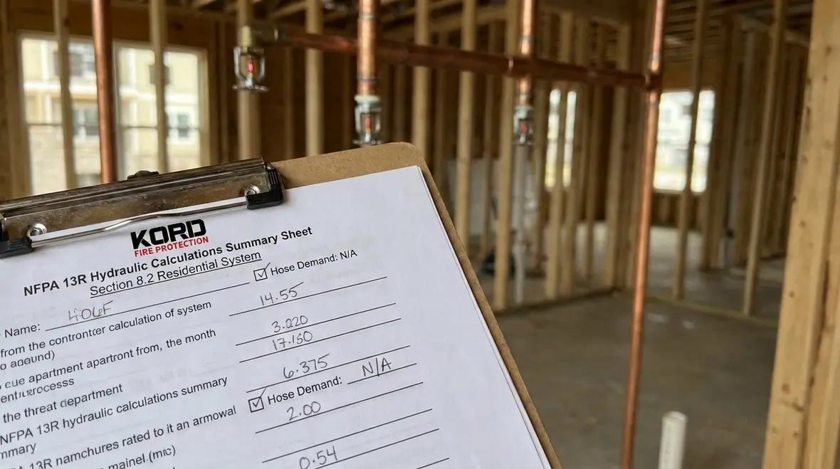
NFPA 13R Section 8.2: Hydraulic Calculations and the Summary Sheet for Residential Systems
Quick Answer
NFPA 13R Section 8.2 requires hydraulic calculations for residential sprinkler systems and a summary sheet that records key design results. When no hose demand is allowed or applicable, the summary sheet must still document demand, flows, pressures, and node selections clearly for review and inspection.
What NFPA 13R 8.2 is asking for, in practical terms
NFPA 13R Section 8.2 hydraulic calculations and the summary documentation translate the design intent into verifiable numbers. In day to day commercial practice, the most common compliance failures do not come from “bad math” alone. They come from incomplete node documentation, unclear demand assumptions, and summary sheets that do not match the hydraulic model used during design.
For teams searching for NFPA 13R 8.2 hydraulic calculations summary sheet no hose demand, the key concept is not simply removing hose demand lines. The designer still must define the system demand basis, pressures at critical points, and the performance of the water supply and piping layout as modeled and as installed.
If you want a broader look at how documentation, inspections, and service all connect in the field, see this fire protection services guide by Kord experts. It fits naturally with the calculation package mindset because design paperwork only helps if the installed system and service record stay aligned over time.
For background on installation workflow that leads into the hydraulic calculation package, review this overview: NFPA 13 overview for automatic sprinkler system installation. While NFPA 13R differs from NFPA 13, the documentation and installation alignment principles carry over directly.
Hydraulic calculations under NFPA 13R 8.2: what gets calculated
Hydraulic calculations determine whether the system meets required performance at the design points. For residential systems designed under NFPA 13R, the calculation package typically includes these elements.
1) Design area and sprinkler selection
Sprinklers are selected based on the intended hazard classification and the spacing criteria applicable to the occupancy and system type. The calculated discharge characteristics and K factors become the foundation for the flow and pressure requirements at the remote points.
2) Node method and pipe loss paths
The calculations convert the piping network into flow paths connected to nodes. Each segment uses internal roughness and length to compute friction loss. Practical compliance issue: when installers field route piping differently than the design set, the friction loss and flow distribution change, but the summary sheet may not reflect the updated final configuration.
3) Water supply performance and elevation effects
Design accounts for available water pressure or pump curve characteristics, static and residual pressures where applicable, and elevation differences between the supply source and the remote area. In commercial and multi tenant retail environments, water supply data often comes from existing systems, and accuracy of residual readings becomes critical.
4) Critical remote area performance
The hydraulic model identifies the remote area that results in the greatest demand or least available pressure margin. The summary documentation must clearly show which remote location and which operating scenario produced the design criterion.
Summary sheet essentials when there is no hose demand
The phrase “no hose demand” often appears in calculation packages where the system is not required to include a hose allowance or where system design criteria exclude hose streams. However, the summary sheet must still be coherent for plan review, inspection, and future troubleshooting.
Document the demand basis clearly
When there is no hose demand, the summary sheet should explicitly show that the system demand is driven by sprinkler discharge alone. The sheet should still include:
- Design sprinkler discharge flow rate used in the demand totals
- Total system flow for the design remote area
- Measured or assumed system supply pressure basis
- Computed pressure at the critical remote point after pipe loss
- Safety factors or margin logic used by the designer, where required by the applicable approach
Keep “no hose demand” consistent across the model, sheets, and drawings
Commercial facility standards frequently require that the calculation narrative, hydraulic model, and the final as built drawing set align. Common failure point: the piping changes or valve selections are updated late in the project, while the summary sheet still carries older assumptions, including hose demand values that were removed from the main calculation narrative but not fully reflected in the summary.
Ensure inspection readiness for installers and authorities having jurisdiction
Inspectors often verify that the system’s installed configuration can support the documented performance. If no hose demand is included, inspectors still expect the summary sheet to allow verification of the sprinkler remote area performance without “hidden” demand additions.
For pump and water supply design concepts that often affect pressure availability, see practical industry resources at firepumps.org. While not NFPA 13R specific, it strengthens understanding of pump curve and water supply dynamics that feed hydraulic calculations.
Operational procedures: how teams prevent calculation to field mismatches
Hydraulic calculations only prove the design if the installed system matches the calculation assumptions. Strong operational procedures reduce rework, delays, and compliance risk in commercial, industrial, and retail facilities.
Pre installation hydraulic model verification
Before fabrication and rough in, design and installation teams should verify the following against the latest drawings:
- Pipe sizes and fittings included in the hydraulic loss model
- Routing offsets, elevation changes, and main sizes
- Valve selections and their pressure loss characteristics
- Sprinkler type, K factor, and temperature ratings
- Any late design change that alters the critical remote path
Pressure and flow test alignment
When the system includes pumps, jockey pumps, tanks, or water supply constraints, the test results must feed the calculations used for final submittals or post modification. Where test data is outdated, the summary sheet can become inaccurate even if the calculations were technically correct at the time of design.
As built updates to the summary sheet
After commissioning and verification, the summary sheet should reflect the installed remote area that controls. When no hose demand exists, the summary should remain simple and unambiguous, but it must still show the full computed performance at the design discharge and pressure condition.
Maintenance and ongoing compliance: protecting the hydraulic record
In real facilities, compliance is a living process. The hydraulic calculation record and summary sheet support recurring inspections and internal audits. Maintenance teams should treat the hydraulic documentation as part of the system’s critical technical history.
What breaks over time
- Partial valve replacements, incorrect strainers, or modified valve positions
- Pipe corrosion, sediment, or changes in interior roughness that alter friction loss
- Sprinkler replacements after activations or impairment corrections that use incorrect characteristics
- Unauthorized alterations in remote branch routes during tenant fit outs
How commercial service providers support compliance
Kord Fire Protection supports ongoing compliance by coordinating system documentation review, testing verification, and maintenance actions that preserve hydraulic design intent. This reduces the risk that the “no hose demand” summary basis becomes inconsistent with the actual installed performance during future inspections and permit renewals.
Common review and approval problems with 8.2 summary sheets
Plan reviewers and inspectors most often raise issues that point back to summary sheet clarity, not just calculation math.
- Unclear demand definition: summary totals do not explicitly show that the demand basis excludes hose demand.
- Wrong remote node identified: the summary sheet labels a remote area that does not match the most hydraulically demanding path from the model.
- Missing pressure at critical points: the sheet lists total flow but omits computed pressure at the design discharge location.
- Inconsistent inputs: the piping lengths, pipe sizes, or fitting selections in the summary do not match the hydraulic calculation report.
- As built gaps: revisions occur during installation, but the summary sheet is not updated to reflect those changes.
These problems become more likely in commercial and industrial facilities where multiple trades access mechanical routing. A disciplined documentation control process is usually the difference between a smooth approval cycle and repeated resubmittals.
Frequently Asked Questions
Call to action
Ensure your NFPA 13R 8.2 hydraulic documentation stays inspection ready by validating the hydraulic model, confirming the “no hose demand” basis is reflected in the summary sheet, and updating records after any field changes. Kord Fire Protection can support ongoing compliance through documentation review, testing alignment, and maintenance planning tailored to commercial, industrial, and retail environments. Request a compliance check today and reduce the risk of resubmittals and performance gaps.

Join Our Newsletter!
Get the latest fire safety tips delivered straight to your inbox From our Newsletter.