NFPA 13D Section 10.4: Pipe Sizing Methods for Residential Sprinkler Hydraulic Calculations
Quick Answer: NFPA 13D Section 10.4 requires pipe sizing based on specific hydraulic calculation methods that match the system design assumptions, including demand, friction loss, and available water supply. Correct selection of the sizing method reduces under designed piping, improves flow testing accuracy, and supports inspection readiness.
If your team is trying to connect the math to real world installation choices, Kord Fire’s sprinkler system hydraulic calculations basics is a helpful companion read before you start chasing pressure losses like they owe you money.
What NFPA 13D Section 10.4 requires and why pipe sizing consistency matters
NFPA 13D Section 10.4 pipe sizing methods residential sprinkler hydraulic calculations NFPA 13D focus on converting sprinkler demand and system constraints into correct pipe sizes. In practice, the method selection impacts friction loss calculations, the assumed design area, hose stream considerations where applicable, and the way installers document system performance for acceptance testing.
For commercial, industrial, and retail environments that rely on residential sprinkler rules for specific protected areas, the compliance challenge often appears during handoff: the as built piping differs from the hydraulic model, pressure gauges do not match the calculation setup, and maintenance teams cannot reconcile system performance after obstructions, valve changes, or minor reconfigurations.
To support safe and compliant installations, organizations typically coordinate design assumptions with field verification. For a broader installation and systems overview, see NFPA 13 overview for automatic fire sprinkler system installation.
Which “pipe sizing method” elements control the hydraulic result
Section 10.4 centered pipe sizing methods operate through a consistent chain of assumptions. Even when two designers use the same general approach, results can diverge if any control element changes.
1) Design basis and sprinkler demand representation
The hydraulic model must reflect the system’s intended operating conditions. Key variables include the sprinkler type, temperature rating, pressure requirements, and the discharge basis used by the calculation method. If the model does not match actual sprinkler listing parameters or the wrong K factor is applied, the friction loss “fit” can look correct on paper while failing during water supply verification.
2) Pipe friction loss computation and fittings strategy
Pipe sizing is driven by pressure loss from friction and the equivalent effect of fittings and valves. Common failure points include:
- Using incomplete fitting lists for elbows, tees, reducers, and check valves.
- Omitting hose connections or auxiliary drains that exist in the field.
- Applying conservative or nonconservative loss assumptions inconsistently between branches.
- Mixing pipe material roughness or Hazen Williams C values that do not match the actual pipe product.
3) Water supply availability and pressure measurement alignment
Pipe sizes only perform as designed when available pressure and flow are measured and modeled correctly. Maintenance teams also need the calculation to align with how acceptance and periodic inspections measure system performance. If the system piping is modified, the pressure gauge location must still represent the modeled hydraulics, or test results become difficult to interpret.
How professionals apply NFPA 13D Section 10.4 pipe sizing methods in the field
Pipe sizing under Section 10.4 often looks like a documentation exercise, but compliance depends on operational procedures. The method becomes defensible when it stays consistent through design, installation, and commissioning.
Step-by-step execution workflow
- Confirm system identity and listing parameters: Verify sprinkler type and orifice size, temperature rating, and K factor from submittal documents and labels. Record exactly what the hydraulic model uses.
- Build the hydraulic layout from field reality: Use the final piping routing, not a preliminary layout. Include stub outs, drain routes, check valve assemblies, and any off branch interconnections.
- Run hydraulic calculations with controlled assumptions: Apply the friction loss approach required by the selected pipe sizing method within Section 10.4. Maintain a calculation workbook that shows inputs and intermediate pressures along each critical path.
- Verify water supply data and document test points: Ensure the modeled demand aligns with the measured supply. Confirm static and residual pressures, flow rates, and hose stream considerations when used by the design basis.
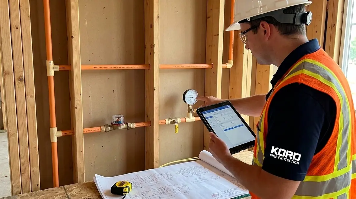
- Execute installation checks before closing walls: Compare pipe sizes and branch configurations to the calculation. Spot check at least the branches that the calculation identified as critical.
- Commission the system with acceptance oriented testing: Confirm that the pressure results, drain flow behavior, and valve performance support the modeled outcomes. Document test results for ongoing inspection readiness.
Commercial stakeholders often expect sprinkler systems to remain stable between acceptance and periodic internal inspections. Kord Fire Protection supports this lifecycle by coordinating documentation, field verification, and maintenance planning so system performance stays aligned with the hydraulic intent.
Common compliance and maintenance issues that derail hydraulic performance
Even with correct selection of NFPA 13D Section 10.4 pipe sizing methods residential sprinkler hydraulic calculations NFPA 13D, real world conditions can change. The following issues frequently create discrepancies during commissioning or subsequent inspections.
Under sizing from hidden branch changes
Small design changes such as rerouted branches, added valves, or revised manifold configurations can alter friction loss and pressure availability. Contractors often treat these as “minor,” but hydraulic demand pathways can shift quickly when critical branches change.
Fitting and valve omissions during documentation
Hydraulic calculations are only as good as their inventory of fittings and control valves. Common oversights include pressure reducing valves, check valves, and air release devices that appear in the field but not in the calculation dataset.
Maintenance impacts on system hydraulics
Over time, debris, partial valve closure, or out of tolerance strainers can reduce effective flow. If hydraulic documentation does not capture those devices and their operational intent, later technicians cannot confidently correlate test performance to the original design basis.
Pressure gauge and test connection mismatch
If acceptance testing uses a different test location than the hydraulic model, measured pressures can mislead. This mismatch often triggers rework, including re sizing, because the team cannot prove whether the issue is the model or the measurement setup.
Supporting resources and calculation readiness
Many design and commissioning teams use reference materials for pump and water supply analysis, system flow verification, and field test planning. For broader context on water supply and fire pump considerations, reference this fire pump testing guide. While Section 10.4 pipe sizing methods address sprinkler hydraulic modeling, water supply characterizations determine whether designed pipe sizes achieve the required operating pressure and flow.
In commercial and mixed use facilities where multiple systems may interface with the same water supply, Kord Fire Protection helps coordinate verification so that the hydraulic model, pump performance, and field testing align. This reduces avoidable shutdown time and shortens the path to acceptance and ongoing compliance.
Frequently Asked Questions
Call to action
Ensure your NFPA 13D hydraulic calculations remain defensible from submittal to acceptance to inspection. Kord Fire Protection supports commercial, industrial, and retail owners with verification planning, documentation control, and maintenance aligned to the installed system configuration. Contact Kord Fire Protection to review your Section 10.4 basis, confirm pipe sizing assumptions against the field layout, and establish a maintenance pathway that protects hydraulic performance.

Join Our Newsletter!
Get the latest fire safety tips delivered straight to your inbox From our Newsletter.