NFPA 30 Section 23.4 UST Location Requirements: How to Meet Underground Tank Siting Rules
Quick Answer
NFPA 30 Section 23.4 UST location requirements set strict siting and separation expectations for underground storage tanks (USTs). The rules focus on protecting public and facility safety by controlling proximity to ignition sources, structures, and operations, and by ensuring accessible installation and inspection readiness.
What NFPA 30 Section 23.4 covers for underground tank siting
NFPA 30 Section 23.4 UST location requirements address where an underground storage tank can be installed and how its location must manage fire, explosion, and exposure risks. In practical terms, the “location” provisions connect tank siting to real-world hazards found in commercial and industrial facilities: building interfaces, utility corridors, vehicle traffic, spill exposure routes, and the ability to inspect and maintain key components without compromising safety.
Because NFPA 30 coordinates fire protection expectations with the broader tank system, a facility should treat Section 23.4 as a siting and operational readiness standard, not just a permitting checklist. A compliant location supports downstream obligations such as integrity testing, corrosion control monitoring, and venting system management.
Facilities commonly overlook how “location” affects ongoing compliance. When tank access hinders inspection work, operators push maintenance activities to shortcuts, which increases the likelihood of hidden defects in piping, leak detection systems, and backfill conditions.
Start with the site reality check: boundaries, interfaces, and access
Before finalizing tank placement, safety teams typically perform a location readiness review that includes four elements: environmental boundaries, structural interfaces, traffic and impact zones, and maintenance access. NFPA 30 Section 23.4 UST location requirements support these outcomes by requiring that tanks sit where hazards and operational impacts remain controlled.
For facilities also evaluating broader commercial system planning, commercial fire suppression services can fit naturally into the discussion when site changes affect hazard controls, inspection readiness, and code coordination.
1) Structural interfaces that increase fire exposure risk
Commercial and retail settings often place tanks near buildings, canopies, loading areas, and service corridors. Close proximity can increase the potential for fire spread if a release occurs or if vapors accumulate. The facility must evaluate how the tank location relates to foundations, service penetrations, and adjacent openings.
2) Traffic, vehicle impact, and excavation control
Underground tanks remain vulnerable to damage from surface loading, excavation, and future utility work. Tank location determines how easily contractors can identify and protect lines during repairs. When tanks sit in high traffic zones without appropriate protective measures, repeated mechanical stress can lead to corrosion acceleration and leak detection impairment.
3) Inspection and maintenance accessibility
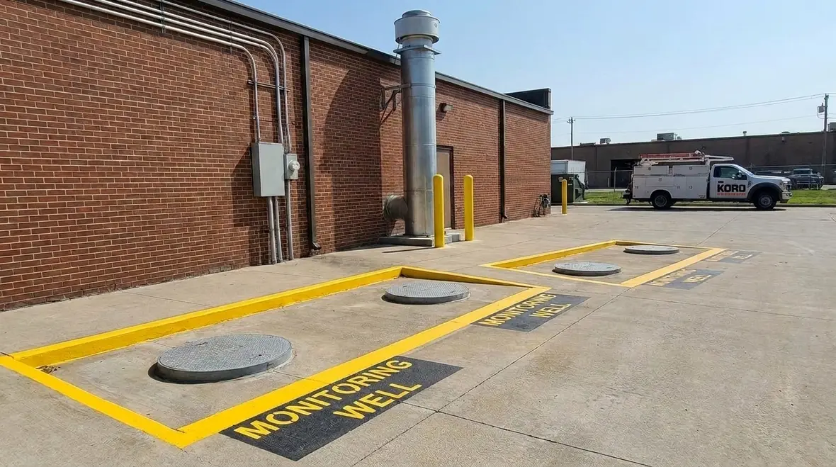
A compliant location must support inspection and maintenance activities. Crews need safe work access to manways, monitoring points, vent terminations, and corrosion control test stations. If the tank location results in tight access, facilities often rely on ad hoc measures such as partial excavations and delayed corrective actions.
For operational context on how NFPA 30 governs flammable liquids and associated risk controls, facilities can review this guidance: How NFPA 30 regulates flammable liquids.
Separation and proximity: planning for ignition control and release management
The intent behind NFPA 30 Section 23.4 UST location requirements is to reduce ignition potential and limit the consequences of a release. Proximity considerations influence vapor migration routes, accumulation points, and exposure to ignition sources such as electrical equipment, heaters, generators, and vehicle operations.
Vapor behavior drives placement decisions
Even with underground tanks, vapor generation can occur from normal venting, temperature changes, and system pressure variations. Location affects where vapors may travel across grade, collect near openings, or migrate toward ignition sources.
Hydraulic and drainage considerations
Tank location also affects how spills and leaked product move. Surface grading, stormwater pathways, and containment features influence whether a release stays localized or spreads. A facility should confirm that the tank installation location does not place product release routes near building egress pathways, mechanical rooms, or electrical service enclosures.
Utility corridors and electrical installations
Many commercial sites consolidate utilities along common corridors. Those corridors can place piping routes, monitoring lines, or vent discharge areas nearer than expected to ignition-relevant equipment. The best practice involves mapping tank system components and verifying that proximity constraints remain satisfied not only at installation but also after future site upgrades.
Installation interface and mechanical integrity: where failures usually begin
Section 23.4 location requirements indirectly protect system integrity by guiding where components sit and how they can be inspected and maintained. Most UST compliance problems that later trigger enforcement actions do not start with “wrong paper.” They start with installation practices that become difficult to verify because the tank sits in the wrong place or in an inaccessible location.
Backfill, compaction, and corrosion control monitoring
Tank location influences how crews place backfill and manage compaction. Poor backfill conditions can trap moisture, increasing corrosion risk. If monitoring points are inaccessible, operators miss early warning indicators tied to cathodic protection performance or corrosion control test results.
Piping runs and joints: location affects inspection feasibility
Piping configurations often extend from the tank to dispensers or product draw points. When tank placement forces longer runs or causes sharp routing decisions due to obstructions, facilities increase the likelihood of joint stress and future excavation exposure. Location planning should support straight, protected routing and allow safe inspection of critical transition points.
Access for leak detection equipment and testing
Leak detection depends on the ability to maintain and test the system as required by the applicable sections of NFPA 30 and related referenced standards. An inaccessible installation can delay testing, which can mask gradual failures in sensors, interstitial monitoring components, or associated wiring and alarms.
Commercial compliance workflow: how to verify NFPA 30 Section 23.4 UST location requirements
Facilities typically achieve durable compliance by building a repeatable verification workflow around tank location. This reduces the risk that a once compliant site becomes noncompliant after construction changes, contractor work, or equipment upgrades.
Step 1: Create a location baseline package
- As-built tank plot plan showing tank, piping, vents, and monitoring points
- Clear grade and drainage notes for release pathway awareness
- Identification of nearby ignition relevant equipment and service activities
- Access map for safe maintenance and inspection routes
Step 2: Conduct a hazard and access walkdown
- Confirm that access routes match planned maintenance methods
- Verify that future excavation zones remain identified and protected
- Check for changes to nearby structures and electrical equipment since installation
Step 3: Confirm continuing maintenance readiness
- Ensure monitoring points remain accessible for test and verification activities
- Verify vent terminations and discharge paths remain unobstructed
- Confirm that corrosion control records can be updated without excessive downtime
Where Kord Fire Protection helps
Kord Fire Protection supports commercial, industrial, and retail facilities with ongoing compliance planning, testing coordination, and practical maintenance readiness support. A strong partner helps facilities avoid common failure points by aligning documentation with field realities and keeping inspection and verification schedules on track. This is especially valuable when sites undergo refurbishments, traffic pattern changes, or utility corridor updates.
What to document during audits and inspections
Auditors and insurers often focus on whether the facility can demonstrate that UST location decisions support safe operation over time. Keeping evidence organized reduces disruption and helps teams respond quickly to nonconformances.
Keep these records readily available
- As-built drawings and plot plans referenced to installation dates
- Tank system component layout, including vents and monitoring points
- Inspection and testing records tied to the actual installation location
- Site change logs that could affect proximity, access, or ignition sources
Common audit gaps
- Plot plans that do not match the current site after renovations
- Missing access route documentation for test and maintenance activities
- Delayed corrective actions because corrective access was not planned
Frequently Asked Questions
Next step
If your facility is planning a new UST installation or you are reviewing existing tank siting, engage Kord Fire Protection to help validate location readiness, inspection accessibility, and ongoing compliance support. Contact Kord Fire Protection to schedule a practical compliance review and align maintenance and testing expectations with your current site layout.

Join Our Newsletter!
Get the latest fire safety tips delivered straight to your inbox From our Newsletter.