NFPA 15 Section 6.1 Electrical Clearances: The BIL and Altitude Adjustment Table Explained
Quick Answer
NFPA 15 Section 6.1 sets minimum separation distances for water spray piping and nozzles relative to energized electrical equipment. The Bureau of International Electrotechnical Commission Lightning Impulse (BIL) and altitude adjustment table drive required clearances, especially in classified electrical locations for 13.8 kV and 23.0 kV systems.
If your project team is also reviewing broader water mist system service needs around special hazard protection layouts, it helps to coordinate that early so clearance decisions, nozzle placement, and maintenance planning do not start arguing with each other halfway through the job. For wider context, you can also review NFPA 15 enhancing fire safety with water spray fixed systems.
Why NFPA 15 6.1 electrical clearances become a real field problem
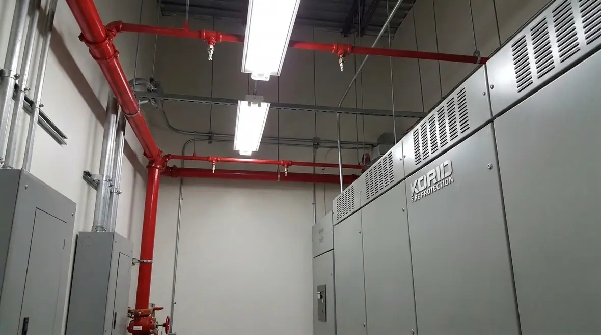
In commercial, industrial, and retail facilities, fixed water spray systems often get installed near electrical gear during fit out, or later as part of hazard upgrades. When sprinkler and water spray piping routes pass through electrical rooms, corridors, and equipment bays, compliance depends on meeting the exacting requirements of NFPA 15 6.1 electrical clearances classified locations 13.8 kV 23.0 kV altitude.
Most inspection failures come from assumptions rather than from the underlying standard. Facility teams may verify voltage once, but they may not confirm the equipment’s impulse withstand level (BIL), the specific classified location boundaries, or the site altitude used for the adjustment factors. Maintenance teams then discover that retrofit work triggers new clearance conflicts that were not present during original design.
What Section 6.1 is actually requiring
NFPA 15 Section 6.1 addresses electrical separation between water spray systems and energized electrical components to reduce the likelihood of electrical flashover, arcing, or conductive paths that may be created or worsened by water discharge.
In practice, the standard translates this intent into measurable distances based on two key inputs:
- Electrical equipment impulse capability expressed as BIL.
- Site altitude which affects dielectric strength of air and the risk of electrical breakdown.
That combination matters most for mid voltage distribution systems (for example 13.8 kV and 23.0 kV), because field teams routinely work with drawings that show voltage but do not clearly label BIL ratings or impulse withstand documentation.
How BIL controls the clearance distance (the design logic)
BIL represents the ability of electrical insulation to withstand a standardized lightning impulse. While nameplate labels commonly identify nominal voltage, they often omit BIL unless the transformer, switchgear, or bus insulation data sheet is pulled. NFPA 15 6.1 clearance calculations depend on the BIL class used by the electrical design.
Clearances increase as the BIL requirement increases because higher insulation withstand levels correlate with higher energy impulse considerations for lightning and switching surges. When BIL is misidentified, the clearance can be under or over specified. Under specifying creates a compliance and inspection failure risk; over specifying can drive costly rework for pipe routing, nozzle placement, and structural attachments.
Common field failure points include:
- Using only “kV” without confirming BIL from equipment submittals or manufacturer test reports.
- Assuming “typical” values because similar equipment was used in another building.
- Failing to update calculations after design changes, such as cable tray relocations or revised nozzle elevations.
- Not coordinating with electrical contractors on the exact boundaries of classified locations and energized components.
How altitude adjustment changes the calculation
Altitude affects air density and dielectric breakdown strength. At higher elevations, air loses insulation capability, so the same physical separation can become less effective. NFPA 15 6.1 therefore incorporates an altitude adjustment approach that modifies the required electrical clearance based on the facility’s elevation.
Commercial facilities frequently experience clearance issues during occupancy transitions, because altitude assumptions often remain tied to master utility models rather than to the actual site survey elevation used for engineering signoff. When a facility expands into a higher elevation service zone or changes the fire protection design basis, teams sometimes reuse prior clearance drawings without verifying the altitude adjustment factor.
Operational takeaway: Electrical clearance work must treat altitude as a verified data point, not a “good enough” design parameter. The clearance measurement should align with the final as built electrical room elevation and the site’s documented height above sea level used by the design engineering record.
Interpreting the “altitude adjustment table” for 13.8 kV and 23.0 kV
NFPA 15 6.1 uses the altitude adjustment table to modify the baseline clearance requirements derived from the equipment BIL class. The typical workflow used by compliance driven engineering teams looks like this:
- Identify the energized equipment near the water spray system. Confirm whether the relevant equipment exists within or adjacent to classified locations.
- Extract the BIL value from the switchgear, transformer, bus duct, or manufacturer documentation. Record the BIL class that corresponds to the standard applied in the electrical coordination documents.
- Determine the facility altitude using the documented site elevation for engineering design and permitting.
- Apply altitude adjustment from the table to determine the required electrical clearance for the water spray system relative to the energized equipment.
- Validate the as installed layout by confirming nozzle and piping positions, hangers, and any flexible connectors. Clearance compliance must be confirmed for the final configuration, not the design intent.
For targets such as NFPA 15 6.1 electrical clearances classified locations 13.8 kV 23.0 kV altitude, the practical outcome typically shows larger required separation distances for higher voltage and higher BIL classes, then further increased by altitude. Facilities located at higher elevation commonly need the most layout changes, including reroutes, relocated nozzle patterns, and revised nozzle elevation to preserve shielded paths or separation geometry.
Where electrical equipment is installed close to water spray coverage points, the design often requires a coordinated approach across fire protection, electrical engineering, and field construction to prevent repeated failures during pre commissioning checks.
Commercial compliance workflow that reduces inspection rework
To control risk, facility teams should adopt a repeatable clearance workflow that treats NFPA 15 6.1 electrical clearances as an installation acceptance requirement, not a later documentation exercise.
1) Build a clearance register early
Create a register that lists each energized electrical item near water spray piping, the confirmed BIL value, the voltage class, and the applicable altitude adjustment factor. Tie each item to plan drawing revision history and as built asset tags.
2) Confirm classified location boundaries
Many sites have hazardous area classifications or electrical room zoning that impacts how inspectors evaluate proximity and exposure. Fire protection teams should align with electrical contractors on where “classified locations” boundaries exist relative to the spray system piping routes and discharge points.
3) Verify during rough in and final inspection
Measure clearances with the installation in its final or near final configuration. Pay special attention to common installation drift points such as:
- Misplaced hangers that shift piping elevation by inches to feet.
- Valve trains, strainers, and fittings that extend toward equipment.
- Conduit, cable trays, and bracketing that change the obstruction profile.
- Flexible sections and coupling assemblies that alter the effective clearance envelope.
4) Plan for maintenance and future modifications
Inspections do not stop at commissioning. When electrical equipment is replaced, upgraded, or reconfigured, the BIL documentation and clearance geometry can change. The maintenance plan should require re verification if any of the following occur:
- Switchgear or transformer replacement with different insulation or impulse withstand data.
- Bus duct or cabling changes that alter equipment dimensions or location.
- Piping reroutes, nozzle replacement, or hanger modifications for leaks or serviceability.
For ongoing water spray fixed system compliance support and structured service processes, Kord Fire Protection positions commercial teams to keep engineered layouts compliant through testing, inspections, and maintenance. Depending on your region, you can also find local industry context and fire pump and water based system education at firepumps.org. For additional Kord resources and regional service coverage, see kordfire.com.au and kordelectric.com.
Frequently Asked Questions
Call to action: lock in compliance before commissioning
Clearances governed by NFPA 15 6.1 electrical clearances classified locations 13.8 kV 23.0 kV altitude require correct BIL documentation, accurate altitude input, and confirmed as built geometry. Kord Fire Protection helps commercial facilities reduce inspection rework by validating clearance assumptions, coordinating field measurements, and supporting ongoing maintenance and testing for water spray fixed systems. Engage a compliance focused team early to protect schedule, budget, and approval outcomes.

Join Our Newsletter!
Get the latest fire safety tips delivered straight to your inbox From our Newsletter.