NFPA 15 Section 9.2: Sizing Water Supply Flow, Pressure, and Duration for Water Spray Systems
Quick Answer
NFPA 15 Section 9.2 sets the method for determining the required water supply flow, pressure, and system duration. For NFPA 15 9.2 volume and pressure flow duration simultaneous systems, designers account for the number of operating sprinklers or spray nozzles, remote hazards, and credible demand conditions to sustain discharge long enough for fire control or knockdown.
For broader context on how fixed spray systems fit into real facility planning, it helps to review NFPA 15 water spray fixed systems in Australia before diving deeper into Section 9.2.
What NFPA 15 9.2 really governs in water spray system design
NFPA 15 Section 9.2 is where the design moves from hazard assumptions into hydraulic reality. It governs how the water supply must perform to deliver the required flow rate, adequate pressure, and required duration to the water spray nozzles during the credited scenario. In commercial facilities, the most common compliance problem is not the concept of “more water,” it is sustaining the correct pressure and discharge over time while meeting real operational constraints such as pump curves, jockey control stability, suction conditions, and interlocked flow logic.
When multiple zones or systems can operate at the same time, NFPA 15 9.2 volume and pressure flow duration simultaneous systems drives the sizing basis. That means the water supply must be sized for the combined credible demand, not for a best case where only one area operates.
How NFPA 15 Section 9.2 ties volume, pressure, and duration together
1) Volume flow demand: translating nozzle requirements into water supply needs
NFPA 15 does not allow a designer to size the supply purely by pipe diameter or pump preference. Section 9.2 requires the system water supply to meet the calculated discharge flow at the intended flow demand points. For water spray systems, the discharge is driven by nozzle design, spacing, and activation characteristics, and then aggregated across the operating portion of the system.
In practical terms, designers must verify that the combination of:
- Operating areas or zones that can release concurrently
- Number of spray nozzles flowing and their discharge coefficients
- Effective area assumptions where permitted
- Changes in demand if the system uses remote actuation or deluge logic
produces a total flow demand that the water supply can sustain.
2) Pressure demand: meeting nozzle and system losses at the operating point
NFPA 15 Section 9.2 requires the supply pressure to satisfy both the nozzle operating requirements and the system pressure losses. This includes friction losses in piping, fittings, hose connections if applicable, strainers, backflow devices, pressure reducing components if present, and any sectional isolation valves that affect the hydraulic path.
Commercial compliance issues frequently appear at the intersection of hydraulics and operations:
- Pump curve mismatch where the actual duty point falls below the pressure required at design flow.
- Strainer or filter partial clogging raising head losses and lowering nozzle pressure.
- Control valve behavior where a valve closes slowly, overshoots, or oscillates under remote starting conditions.
- Pressure setpoint drift in jockey pumps or controllers after maintenance.
3) Duration: ensuring the supply remains capable long enough
Duration is not a paper calculation. Water supply duration must be practical for the hazard credibility scenario and meet the standard’s requirements. In water spray systems, duration ties directly to tank sizing or pump run time capability and fuel supply for diesel systems, plus the ability of the pumps to remain within acceptable operating ranges during sustained discharge.
From a maintenance and inspection standpoint, duration calculations must match actual installed hardware. Facilities often discover late that:
- Water tank usable volume is lower than expected due to intake arrangement or level gauge calibration.
- Pump suction conditions degrade over time due to debris, water quality changes, or suction line issues.
- Pressure maintenance devices reduce available pressure during long runs because control logic was not commissioned to the final configuration.
When NFPA 15 9.2 volume and pressure flow duration simultaneous systems become the sizing driver
Simultaneous operation changes everything. In a commercial facility, multiple hazards can exist in the same building zone, and fire detection, water spray control panels, or deluge release logic can bring multiple flow paths online together. NFPA 15 9.2 volume and pressure flow duration simultaneous systems ensures designers size the water supply for the credible combined demand, including the pressure needed to deliver discharge during the credited period.
Common simultaneous demand scenarios in commercial and industrial buildings
- Linked or zoned control logic where more than one spray area can actuate by design.
- Deluge style water spray where multiple manifolds can open together from a single alarm or control event.
- Shared water supplies serving multiple fixed systems in the same hydraulic installation.
- Remote supervisory and emergency power behavior that could permit pump start sequences to overlap.
Operational failure points to watch during acceptance and ongoing service
Simultaneous systems tend to expose weaknesses in commissioning and maintenance:
- Undersized pump staging leading to an initial surge of flow that decays as pressure falls under friction and partial valve throttling.
- Flow balancing problems where one branch path receives more pressure and flow, starving another nozzle field.
- Valve position mismatches after maintenance, resulting in isolation valves left partially closed or inadvertently throttled.
- Pressure reducing or control hardware drift over time that undermines the intended discharge distribution.
To reduce risk, facilities should verify performance not only at the single design point but also during the expected multi zone release conditions. Ongoing service then protects that verified performance through inspection, functional testing, and hydraulic checks where required.
Water supply components that determine whether NFPA 15 Section 9.2 will be met
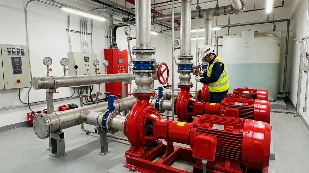
NFPA 15 Section 9.2 outcomes depend on how the installed water supply behaves under flow. The most important commercial components include pumps, controllers, jockey systems, tanks, suction piping, strainers, and flow control valves.
Pumps and controls: the duty point is where compliance happens
Pump performance must align with the required flow and pressure for the simultaneous scenario. Designers and technicians should confirm pump duty points using current measured static and residual pressures and then validate against the pump curve and system losses.
During maintenance, technicians should pay attention to:
- Controller settings and alternation logic
- Pressure transducer calibration and drift
- Air entrainment or cavitation risks on suction
- Backflow preventer and strainer pressure drop
Water storage and endurance: usable volume and sustained suction matters
Where tanks are used, usable volume must support the required duration at the required discharge rate. Over time, facilities can experience changes in tank operation such as intake screen fouling, level transmitter miscalibration, and sediment accumulation that affects suction conditions and pump efficiency.
Valves and appurtenances: small components create big hydraulic losses
Strainers, check valves, control valves, gate or butterfly valves, and backflow prevention equipment can shift the system’s hydraulic balance. Even when the system meets requirements during initial design acceptance, later maintenance can alter installed friction, valve seating condition, and actuator response. Those changes can reduce available pressure at nozzle elevation, particularly under high combined flow.
How commercial facilities should verify and maintain NFPA 15 9.2 compliance
Compliance success depends on verification that reflects the installed condition, not just the design intent. Water spray systems must remain capable of delivering design flow, pressure, and duration after renovations, equipment replacements, and routine service.
Commissioning and acceptance practices that hold up during audits
- Documented hydraulic calculations tied to the final as built configuration, including all credited simultaneous flows.
- Measured pressure and flow verification at operating points that reflect realistic demand and pump control behavior.
- Inspection of isolation and control valves to ensure final positions match the intended flow path.
Ongoing inspection and service routines that prevent drift
- Periodic functional testing of pump controllers and starting sequences, including controller alternation under live supervisory conditions.
- Strainer inspection and cleaning to maintain design pressure losses.
- Verification of suction water conditions where tanks exist, including checks for debris or sediment.
- Assessment of pressure regulating and control components for calibration drift.
For a practical overview of how fixed water spray system enhancements support defensible outcomes in commercial environments, see NFPA 15 enhancing fire safety with water spray fixed systems.
When organizations need credible testing support, pump performance verification, and documentation discipline, Kord Fire Protection supports ongoing compliance through commissioning support, inspection readiness, and maintenance planning aligned with commercial facility realities.
Useful industry references for fire pump and system performance
Because NFPA 15 9.2 performance depends heavily on pump behavior and system hydraulics, facility teams often benefit from cross referencing pump fundamentals and performance verification methods. For pump related context, system sizing concepts, and industry guidance, visit FirePumps.org.
These resources complement on site documentation and testing by reinforcing the engineering reasoning behind duty points, pressure maintenance, and sustained operation. They do not replace local code interpretation, approved plans, or manufacturer instruction.
Frequently Asked Questions
Final call: verify the installed hydraulic reality, not only the design intent
NFPA 15 Section 9.2 sets the performance standard for flow, pressure, and duration, and NFPA 15 9.2 volume and pressure flow duration simultaneous systems makes that performance non negotiable when multiple demands occur together. Kord Fire Protection helps commercial facilities protect compliance with commissioning support, targeted testing, and maintenance that preserves pump duty point performance and system hydraulic losses. Contact Kord Fire Protection to review as built conditions and validate the simultaneous demand basis for your water spray installation.

Join Our Newsletter!
Get the latest fire safety tips delivered straight to your inbox From our Newsletter.