NFPA 17A 7.3 Required Details on System Plans
Quick Answer
NFPA 17A 7.3 requires fire protection system plans to clearly show the wet chemical extinguishing system design, key components, hazards coverage, piping and discharge details, and installation and support information. Well-prepared NFPA 17A plans drawings wet chemical layout help reviewers verify performance and reduce commissioning and maintenance delays.
For a practical system overview near the start, see wet chemical fire suppression systems and Range Guard, which helps connect plan details to real discharge behavior, detection, and protected cooking hazards.
Why NFPA 17A plans drawings wet chemical layout matter at plan review
System plan review is not a paperwork exercise. For wet chemical extinguishing systems, the layout, agent routing, discharge locations, and equipment selection directly determine whether the design can meet the intended suppression performance. NFPA 17A 7.3 focuses on the minimum information needed so the authority having jurisdiction (AHJ), installers, inspectors, and maintenance teams can validate the design without guessing.
Commercial facilities face real constraints during installation and occupancy: tenant turnover in retail, production schedule downtime in industrial spaces, and ongoing inspections in multiuse buildings. If plan sets are incomplete, field changes often trigger rework, delayed approvals, and costly commissioning retries. Kord Fire Protection supports facility owners and contractors with documentation and compliance readiness for wet chemical systems through installation oversight, testing coordination, and ongoing maintenance planning.
NFPA 17A 7.3 plan details: what the drawings must communicate
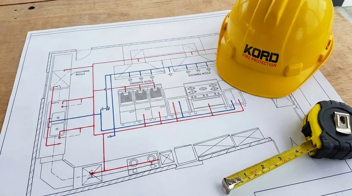
NFPA 17A 7.3 requires system plans to provide specific details that allow the system to be constructed and evaluated correctly. The plans typically need to communicate hazard conditions, coverage strategy, piping and discharge routing, and the arrangement and identification of components. For NFPA 17A plans drawings wet chemical layout, the reviewer should be able to trace agent flow, confirm discharge placement relative to hazard surfaces, and verify that support, materials, and installation methods align with the design criteria.
1) Hazard description and intended protection objective
The plan set must identify the protected hazards and the basis for the hazard classification used to size the system. Wet chemical systems are commonly installed over cooking appliances where grease laden vapors and hot oil presents a unique risk. The design intent must be unambiguous so that installers and inspectors understand what needs to be covered and why.
2) System type, agent, and component identification
Plans must clearly show that the system is a wet chemical extinguishing system and identify the key components that make it work. This includes cylinders or tanks, valves, piping, strainers, pressure elements where applicable, actuation devices, and discharge nozzles or outlets. Component identification matters for maintenance because the correct parts and configuration must match the installed system to avoid substitutions that can affect performance.
3) Layout of piping, routing, and elevation control
Wet chemical discharge performance depends on correct routing and positioning. NFPA 17A 7.3 plan documentation should clearly depict pipe sizes, routing paths, fittings, and elevations. For NFPA 17A plans drawings wet chemical layout, reviewers typically look for a traceable path from the agent container through valves and piping to the discharge outlets.
Common compliance challenge: field routing deviates due to structural obstructions or duct interference. Without clear elevation and routing details, installers can change the plan interpretation, leading to incorrect discharge positioning or strain on supports.
4) Discharge outlet locations and appliance association
Plans must relate discharge outlets to the protected cooking appliances or hazard surfaces. Discharge placement is not generic. The drawings should identify the outlet locations clearly and show how they coordinate with the equipment they suppress. This is a frequent source of delayed approval when outlet drawings are too vague or appliance labeling is missing.
5) Actuation and control sequence representation
Plan sets should indicate the actuation method and the sequence expectation, including how the system triggers and initiates agent discharge. For facilities that use detection and control integrations, the plan information should be consistent with the intended operation and alarm interfaces required by local standards and the facility’s fire alarm strategy.
6) Supports, anchors, and installation constraints
Wet chemical systems rely on stable piping arrangement. The plan set should show details for supports, anchors, and the installation approach that matches the system design. In commercial kitchens, vibration, cleaning access, and tenant modifications can stress piping if supports are not properly detailed. If supports are omitted from NFPA 17A plans drawings wet chemical layout, the contractor may install ad hoc bracing that fails inspection or reduces reliability.
How AHJs and inspectors verify plan adequacy in the real world
Plan review success depends on how directly the drawings allow verification. AHJs typically cross check the system narrative with the layout drawings, component schedules, and hazard coverage details. Inspectors later compare the installed configuration against the approved documents, especially for outlet locations, valve types, and piping arrangement.
What gets missed most often
- Appliance and discharge labeling gaps: outlets shown without a clear reference to the cooking equipment they protect.
- Unclear pipe routing and elevations: drawings show a general path but not enough detail to maintain discharge alignment.
- Incomplete component schedules: missing manufacturer model information can cause substitution issues.
- Support details not carried through: field modifications occur when support locations are not specified early.
- Mismatch between narrative and drawings: a system described one way, but drawn differently.
Kord Fire Protection helps clients address these gaps before installation proceeds, supporting smoother commissioning and fewer re-inspections. For further background on system design and risk reduction using wet chemical suppression, see Enhancing Fire Safety with NFPA 17A Wet Chemical Extinguishing Systems.
Commissioning and maintenance planning starts with the plan set
Strong documentation reduces operational risk. When plans are clear, commissioning can verify that the piping, valves, discharge outlets, and actuation sequence operate as intended. That clarity also supports inspection and maintenance activities over the system’s lifecycle.
Operational checks tied to plan details
- Identification verification: confirm installed components match the plan set and the equipment schedules.
- Outlet position verification: confirm each discharge location aligns with the appliance hazard mapping shown on NFPA 17A plans drawings wet chemical layout.
- Piping integrity verification: verify routing and support conditions match the installed plan and engineered design.
- Actuation and sequence checks: confirm detection and release functions align with the system design intent.
Maintenance failure points often trace back to the drawing stage
Wet chemical systems can fail to perform reliably when critical components are difficult to access for maintenance, when valves or cylinders are not installed as designed, or when discharge outlets become misaligned after renovations. Plans that include correct identification and clear routing reduce the chance of “as built” drift during future tenant work.
For broader guidance on maintaining suppression system performance, refer to Fire Suppression Systems.
Where to find pump and hydraulic reference context (and why it still affects wet chemical)
Even though wet chemical systems use specific agent delivery components, facility designers frequently coordinate multiple suppression systems. Designers and contractors sometimes need hydraulic and flow reference context when systems interface with pumps, water supplies, or combined fire protection strategies.
For general fire protection system context that can support coordinated design reviews, see Fire Pumps. While that resource does not replace NFPA 17A plan requirements, it can help teams align documentation conventions when wet chemical systems coexist with other fire protection systems in a commercial environment.
Frequently Asked Questions
Conclusion and next steps
NFPA 17A 7.3 plan details directly affect approval speed, commissioning success, and long term reliability. A compliant plan set must make the wet chemical system traceable: hazards, outlets, routing, actuation, components, and supports should all match. Kord Fire Protection helps commercial and industrial facilities prepare and maintain documentation that reduces rework and supports inspection readiness. Engage Kord Fire Protection early to confirm your NFPA 17A plans drawings wet chemical layout meets review expectations before construction begins.

Join Our Newsletter!
Get the latest fire safety tips delivered straight to your inbox From our Newsletter.