NFPA 33 Section 5.1: Spray Areas – Construction and Design Basics
Quick Answer
NFPA 33 Section 5.1 defines how spray areas must be built and arranged to control ignition sources, manage hazardous residues, and support safe ventilation and extinguishing features. Facility owners must integrate construction details early, then sustain compliance through inspections, testing, and maintenance.
For facilities looking at broader system reliability alongside enclosure safety, Kord Fire Protection’s fire pump testing requirements guide is a helpful related resource near the top of the planning process.
What NFPA 33 spray area construction design requirements mean in practice
For commercial, industrial, and retail facilities using spraying processes, NFPA 33 spray area construction design requirements translate into measurable construction and design outcomes. These outcomes include controlling how air moves through the spray area, limiting ignition potential, and preventing accumulation of combustible deposits. In real operations, noncompliance often shows up during shutdown inspections, smoke tests, duct cleaning assessments, and post-modification reviews when spray booth layouts or exhaust pathways change.
Where Section 5.1 applies and how spray area boundaries get defined
NFPA 33 Section 5.1 focuses on construction and design basics for spray areas, meaning the space where spraying activities occur and where overspray or residue may migrate. The practical challenge is that “the spray area” is not only the booth or workstation. It can extend to adjacent spaces where air handling, air currents, and waste streams move hazardous vapors, mists, and deposits.
Common boundary mistakes
- Assuming the booth walls alone define the hazard when ventilation patterns or make up air drives overspray beyond the enclosure.
- Changing equipment locations during renovations without revalidating airflow and deposition impacts.
- Leaving doors, transfer openings, or service penetrations uncontrolled where leakage can bypass the intended exhaust path.
Construction controls: enclosure integrity, ignition management, and openings
Section 5.1 requires spray areas to be constructed so that the design intent for hazard control remains effective through daily use and maintenance cycles. In most facilities, the construction questions converge on enclosure integrity, continuity of protective features, and control of openings that can compromise containment.
Enclosure and surface considerations
Spray areas typically require interior surfaces that do not contribute to unsafe fire behavior and that can be cleaned effectively. Deposits from overspray and overspray carrying residues can accumulate on floors, beams, lights, and HVAC components. When surfaces cannot be cleaned or become too contaminated, ignition exposure increases during normal operations such as switching spray patterns, cleaning, or filter changes.
Doorways, walls, and penetrations
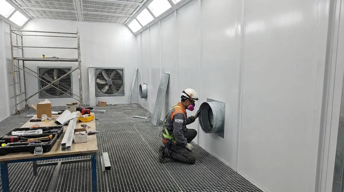
Openings for access, duct penetrations, electrical runs, and hose routing must be built and sealed to preserve safe airflow and reduce uncontrolled leakage. Even when the ventilation system is compliant, a poorly sealed penetration can alter pressure balance and drive hazardous mist outside the intended capture zone.
Ignition source control through construction choices
Construction and design must limit the likelihood that ignition sources can interact with flammable vapors or residues. This includes attention to how electrical components are installed, how cable routes cross the spray area, and how fixtures support safe operation without becoming contaminated or obstructing airflow.
Ventilation and airflow design basics that construction must support
Ventilation is the backbone of spray area safety because it supports capture of mists and vapors and reduces concentration. Section 5.1 ties construction to ventilation effectiveness, meaning the room layout, enclosure performance, and duct pathways must support the designed air movement.
Pressure relationships and airflow stability
Many compliance failures come from unstable airflow caused by construction issues such as misaligned duct dampers, damaged exhaust boots, missing transfer grilles, or improperly installed make up air provisions. Facility teams often discover the problem during commissioning verification or after routine maintenance, when filters, dampers, or fan belts get replaced and performance shifts.
Capture and overspray deposition control
Construction must allow the ventilation system to create consistent capture. If capture is poor, overspray deposits on non intended surfaces and increases ignition exposure during later cleaning or hot work. Operationally, maintenance teams can reduce risk only if construction supports safe access for inspection and cleaning, including filter change procedures and duct access points.
Serviceability and maintenance readiness: where projects usually break down
Spray area construction is not finished at substantial completion. Section 5.1 emphasizes the need for design that supports ongoing control through inspections and maintenance. For commercial facilities, this directly affects compliance costs and operational downtime.
Maintenance access and inspection pathways
Design should provide practical access for:
- Filter replacement and inspection without contaminating surrounding clean areas.
- Verifying exhaust duct integrity and clean out capability.
- Confirming that airflow devices remain aligned and unobstructed.
- Maintaining safe clearance around electrical equipment and lighting.
Common failure points observed in the field
- Damper linkage misalignment after maintenance creates reduced capture and increased deposition.
- Unsealed cable penetrations lead to pressure loss and leakage of mist or vapors.
- Improperly restored modifications such as patched wall sections that no longer match the original sealing or surface characteristics.
- Accumulation that outpaces cleaning due to construction layouts that trap residues in corners and overhead areas.
Commercial compliance strategy: documentation, testing, and ongoing coordination
Facilities should treat NFPA 33 spray area construction design requirements as a living compliance system tied to ventilation performance, housekeeping, and maintenance. The safest approach combines initial design verification with periodic testing that confirms the spray area continues to meet intent after equipment swaps, material changes, and renovations.
What to document for inspection readiness
- As built layouts showing spray boundaries, openings, and airflow pathways.
- Ventilation design basis and performance verification results.
- Maintenance procedures for filters, duct cleaning, and residue control.
- Change control records for any modifications affecting enclosure integrity or airflow.
To strengthen ongoing compliance and reduce operational risk, facilities often partner with Kord Fire Protection for inspection, testing, and maintenance support. For additional NFPA related guidance on coordinated fire protection and safer construction practices, see Kord Fire Protection and request a compliance review tailored to the spray area scope.
Frequently Asked Questions
Next step: validate your spray area before it becomes an inspection problem
Review your spray area boundaries, ventilation support details, and sealing integrity while equipment and ductwork are still accessible. Then schedule a focused compliance and maintenance readiness assessment with Kord Fire Protection to confirm your construction and design continue to meet NFPA 33 intent through daily operations, filter changes, and future modifications.
Join Our Newsletter!
Get the latest fire safety tips delivered straight to your inbox From our Newsletter.